Table of Contents
Advertisement
Advertisement
Table of Contents

Subscribe to Our Youtube Channel
Related Manuals for Chauvin Arnoux C.A 6531


Summary of Contents for Chauvin Arnoux C.A 6531
- Page 1 C.A 6531 MEGOHMMETRES MEGOHMMETERS C.A 6533 MEGOHMMETER MEGAOHMMETRI MEGAÓHMETROS F R A N Ç A I S Notice de fonctionnement E N G L I S H User's manual D E U T S C H Bedienungsanleitung I T A L I A N O Libretto d’Istruzioni...
- Page 2 For safety reasons, this symbol will light up on the LCD screen as soon as a voltage is generated. Thank you for purchasing a C.A 6531 or C.A 6533 insulation tester. To get the best service from this instrument : read this user’s manual carefully...
-
Page 3: Table Of Contents
AC / DC voltage measurement ......29 3.1.2 Insulation Measurement ........30 Resistance ..............30 Capacitance (C.A 6531) ..........31 AC / DC current (C.A 6531) .......... 31 AC voltage (C.A 6531) ..........31 SPECIAL FUNCTIONS ........31 Start/stop ..............31 Automatic shutdown ............. 32 4.2.1... - Page 4 AC / DC voltage and insulation measurement ..... 35 Resistance measurement ..........36 Capacitance measurement (C.A 6531) ......36 AC / DC current measurement (C.A 6531) ....36 AC voltage measurement (C.A 6531) ......36 SPECIFICATIONS ..........37 Reference conditions ............ 37 Characteristics per function ..........
-
Page 5: Presentation
They can be used to check insulation and voltages and to measure resistances. The C.A 6531 can also be used for: measurement of the capacitance of a telephone line current measurement measurement of the pure alternating component of a DC voltage. -
Page 6: Description
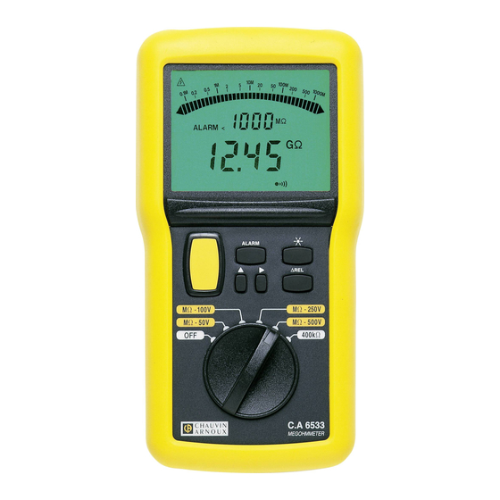
See the diagrams of the instruments in § 10 (appendix at the end of this user’s manual) 2.1.1 C.A 6531 3 safety terminals, Ø 4 mm (marked “mA”, “ + “ and “ - “) Next to the “ – “ terminal, there are two additional contacts for connecting the remote control probe (3-point connector). -
Page 7: Bargraph
Buzzer active Constant operation (no automatic shutdown) Batteries flat 2.2.2 Bargraph Insulation > 1.1 GΩ Insulation < 70 kΩ 2.2.3 Digital display Batteries low – must be changed Range exceeded - - - Insulation < 10 kΩ at 50 V, < 20 kΩ at 100 V, <... -
Page 8: Key
0, 1, 2, 3, 4, 5, 6, 7, 8 or 9. 2.3.5 C.A 6531 and C.A 6533 When this key is pressed, the backlighting of the display comes on. It will be turned off automatically one minute later. When it is lit, you can turn the backlighting off by pressing this key again. -
Page 9: Insulation Measurement
The instrument indicates if the value measured is outside its measurement range. If the insulation resistance is greater than 400 MΩ (C.A 6531), 2 or 20 GΩ (C.A 6533), the OL symbol is displayed on the digital measurement display. When the measurement is greater than 1.1 GΩ... -
Page 10: Capacitance (C.a 6531)
If the leads are not connected, the digital measurement display indicates 0.00 and - - - - km. AC / DC current (C.A 6531) Current measurement corresponds to the 400 mA position of the switch. -
Page 11: Automatic Shutdown
< 6.7 V): the digital display indicates BAT and then, after 5 seconds, the shutdown buzzer sounds and the automatic shutdown function is activated. The instrument shuts down. 4.3.2 Fuse (C.A 6531) The fuse is automatically tested when switching on the instrument and at the end of each current measurement. -
Page 12: Deactivation Of The Buzzer
For example, a 2 GΩ insulation threshold will be stored in the memory as 399.9 MΩ on the C.A 6531, while for resistance measurement 700 kΩ will become 399.9 kΩ on the C.A 6533. -
Page 13: Activation/Deactivation Of The Alarm Thresholds
This key can be used at any time except in voltage mode on the MΩ Ω Ω Ω Ω positions. Programming the capacitance per unit length (C.A 6531) When the switch is set to nF, a long press on the key activates the programming mode for the capacitance per unit length of the line to be measured. -
Page 14: Use
During programming, if you change the switch position, you lose what you have just done. You can quit the programming mode and record the value by another long press on the key. 5. USE To display the device software version and series number press the yellow button whilst switching on via the rotating switch. -
Page 15: Resistance Measurement
Resistance measurement Start up the instrument by setting the switch to 40 kΩ (C.A 6531) or 400 kΩ (C.A 6533). Connect the + and - leads to the measurement points. Note the resistance value displayed (see § 3.2). Note: The user can control the backlighting as required by pressing the key. -
Page 16: Specifications
0.1 V Accuracy ± 3% R ±2 ct ± 3% R ±1 ct Input impedance 4 MΩ (C.A 6531) - 300 kΩ (C.A 6533) 6.2.2 Insulation Measurement range: C.A 6531: at 50 V 10 kΩ to 400 MΩ at 100 V 20 kΩ... -
Page 17: Resistance
3 to 6 s/µF according to the measurement for the C.A 6531 and in less than 2 s/µF for the C.A 6533. 6.2.3 Resistance Measurement range : 0 to 40 kΩ for the C.A 6531 0 to 400 kΩ... -
Page 18: Ac Voltage (C.a 6531)
6.2.7 AC voltage (C.A 6531) Measurement range: 0 to 399.9 V AC Frequency: 10 Hz to 1 MHz Resolution: 0.1 V AC Accuracy: ± 3% R ± 3 ct Internal impedance: 4 MΩ Power supply The instruments are powered by 6 x 1.5 V alkaline batteries, type LR6. -
Page 19: Variations In Nominal Field Of Use
C.A 6531, and 720 V AC/DC on the C.A 6533. The C.A 6531 is protected for 10 s against an accidental overvoltage of 720 V across all the ranges. The current input on the C.A 6531 accepts 0.63 A, beyond which it is protected by fuse. 6.7. Construction specifications Overall dimensions of the unit (L x l x h): 211 x 108 x 60 mm Dimensions of the display: 73 mm x 54.3 mm... -
Page 20: Electromagnetic Compatibility: Ec Compliance
1.5 V batteries should be mounted. Make sure that you put the hatch back properly and close it after changing the batteries. 7.1.2. Replacing the fuse (C.A 6531) If “FUS” appears on the digital measurement display during the start-up phase or when measuring continuity, you must change the fuse, taking all the necessary precautions when opening the instrument. -
Page 21: Cleaning
We advise you to check this instrument at least once a year. For checking and calibration of your instrument, please contact our accredited laboratories (list on request) or the Chauvin Arnoux subsidiary or Agent in your country. 7.2. Maintenance... -
Page 22: To Order
9. TO ORDER C.A 6531 ............... P01.1408.04 Delivered with a shoulder bag for transport and hands-free use of the instrument and its accessories, 2 elbowed-straight safety leads (red +black), 1.5 m long 1 red crocodile clip, 1 black touch prod, 2 wire grips (red and black), 6 LR6 batteries and this 5-language user’s manual.
Need help?
Do you have a question about the C.A 6531 and is the answer not in the manual?
Questions and answers