Table of Contents
Advertisement
Quick Links
Advertisement
Table of Contents

Related Manuals for Chauvin Arnoux C.A 6536


Summary of Contents for Chauvin Arnoux C.A 6536
- Page 1 GB - User’s manual C.A 6536 Megohmmeter...
- Page 2 The product is declared recyclable following an analysis of the life cycle in accordance with standard ISO14040. Chauvin Arnoux has adopted an Eco-Design approach in order to design this appliance. Analysis of the complete lifecycle has enabled us to control and optimize the effects of the product on the environment. In particular this appliance exceeds regulation requirements with respect to recycling and reuse.
- Page 3 PRECAUTIONS FOR USE This instrument is compliant with safety standard IEC 61010-2-030 and the leads are compliant with IEC 61010-031, for voltages up to 600 V in category IV or 1,000 V in category III. Failure to observe the safety instructions may result in electric shock, fire, explosion, and destruction of the instrument and of the installations.
-
Page 4: Table Of Contents
CONTENTS 1. PRESENTATION ..................................5 1.1. Delivery condition ................................5 1.2. Accessories ..................................6 1.3. Replacement parts ................................. 6 1.4. Presentation of the instrument ............................7 1.5. Terminal block ................................9 1.6. Functions of the instrument ............................9 1.7. Function keys ................................. 9 1.8. -
Page 5: Presentation
Do not use alcohol, solvents, or hydrocarbons. Do not modify the leads or accessories. Any non-compliant repairs can cause risks of electric shock or burns. One C.A 6536. Two straight/right-angle safety leads (red and black). One red crocodile clip. -
Page 6: Accessories
1.2. ACCESSORIES Type 3 remote control probe Continuity pole Thermometer + K thermocouple, C.A 861 Thermo-hygrometer C.A 846 1.3. REPLACEMENT PARTS 2 straight/right-angle safety leads (red and black) 1.50 m long 2 crocodile clips (red and black) 2 test probes (red and black) 2 wire grips (red and black) Carrying case that also allows hands-free use For accessories and spare parts, visit our website:... -
Page 7: Presentation Of The Instrument
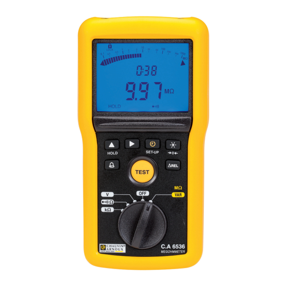
1.4. PRESENTATION OF THE INSTRUMENT 1.4.1. C.A 6536 Connection terminals. Backlit digital display unit. M mAµA < > ALARM HOLD 6 function keys. TEST TEST button to start the measurements. Ω Ω Ω Five-position switch to choose the function or to switch the instrument off. - Page 8 1.4.2. ON THE BACK Captive quarter-turn screw. Battery compartment cover. Magnet for attachment to a metallic surface. Non-skid pads. Prop.
-
Page 9: Terminal Block
> 700V 600V CAT IV 1.6. FUNCTIONS OF THE INSTRUMENT The C.A 6536 megohmmeter is a portable measuring instrument with digital display. It is powered by batteries. C.A 6536 Test voltages for insulation measurements from 10 V to 100 V in... -
Page 10: Test Button
1.8. TEST BUTTON The TEST button is used to make insulation measurements. 1.9. DISPLAY Logarithmic bargraph to display insulation measurements. DARPI T1T2 G VHz % M mAµA < > Secondary display unit. ALARM k nF/ km G nF µF Main display unit. HOLD When the measured value is below the minimum, the instrument displays - - - - . -
Page 11: Use
2. USE 2.1. GENERAL At start-up, the instrument indicates the remaining battery If the battery voltage is too low to ensure correct operation life. of the instrument, it so reports. G VHz The batteries must then be replaced (see § 4.2)), since the battery life indication is no longer reliable. -
Page 12: Insulation Measurement
2.3. .INSULATION MEASUREMENT Ω Ω Set the switch to the MΩ position. Ω The instrument displays the programmed test voltage. To modify the test voltage (between 10 et 100 V), press the key. When the first digit blinks, you can change it using the key. Press to go to the next digit and ... - Page 13 At the end of the measurement, release the TEST button. The instrument stops generating the test voltage and discharges the device being tested. The symbol is displayed until the voltage on the device has fallen below 70 V. Do not disconnect the leads and do not start any measurement while the symbol is displayed.
-
Page 14: Continuity Measurement
Press the TEST key to return to the voltage measurement. TEST 2.3.3. REMOTE CONTROL PROBE (OPTION) The remote control probe is used to trigger the measurement using the remoted TEST button on the probe. To use this accessory, refer to its operating instructions. When the probe is connected, the symbol is displayed. - Page 15 2.4.1. COMPENSATION OF THE LEADS To ensure precise measurements, it is necessary to compensate the resistance of the measurement leads. Short-circuit the measurement leads and long-press the key. > 2s The display changes to zero and the symbol is displayed. The resistance of the leads will be systematically subtracted from all continuity measurements.
-
Page 16: Resistance Measurement
2.4.3. MAKING A MEASUREMENT Use the leads to connect the device to be tested to the terminals of the instrument. The device to be tested must not be live. The instrument makes the measurement directly. It displays the result and the measurement current. -
Page 17: Rel Function
2.6. ∆REL FUNCTION For an insulation or resistance measurement, it is possible to subtract a reference value from the measured value and display the difference. To do this, make a measurement, then press the ∆REL. The main display changes to zero and the ∆REL The measurement (Rref) is stored and subtracted from symbol is displayed. -
Page 18: Backlighting
2.8. BACKLIGHTING Pressing the key switches on the backlighting of the display unit. To switch it off, press the key again. Otherwise, it goes off by itself at the end of one minute. 2.9. SET-UP A long press on the SET-UP key is used to enter the configuration (set-up) function of the instrument. >... -
Page 19: Alarm Function
2.10. ALARM FUNCTION Pressing the key activates the alarm. The alarm function symbol is displayed, along with the threshold, on is available in insulation, resistance, and continuity the secondary display unit. measurements. < ALARM While it is displayed, you can change this value using the key, except during insulation measurements. For each position of the switch, there are 3 pre-recorded threshold values: „... -
Page 20: Automatic Stop
2.11. AUTOMATIC STOP After 5 minutes of operation with no sign of the user’s presence (key press or rotation of the switch), the instrument switches to standby. Simply press any key to exit from standby. The instrument returns to the state it was in, with no loss information: value of the last measurement, compensation of the leads, ∆Rel, timed mode, alarm, etc. -
Page 21: Resetting The Instrument
2.13. RESETTING THE INSTRUMENT If your instrument crashes, it can be reset like a PC. Then turn the switch. Press the and keys simultaneously. Ω Ω Ω The instrument reboots. -
Page 22: Technical Characteristics
3. TECHNICAL CHARACTERISTICS 3.1. GENERAL REFERENCE CONDITIONS Quantity of influence Reference values Temperature 23 ± 3 °C Relative humidity 45 to 55% RH Frequency DC and 45 to 65 Hz 8 ± 0.2V Supply voltage battery life indication 58 ± 8% Electric field 0V/m Magnetic field... - Page 23 Bargraph Specified measurement range 0,1 MΩ - 50 GΩ * Resolution 9 segments per decade Intrinsic uncertainty ± (5% + 1 segment) **: When the measurement range is exceeded, the whole bargraph is displayed. Test voltage With a test current < 1mA, the intrinsic uncertainty on U is ±...
-
Page 24: Variation In The Range Of Use
*: In the case of incorrect compensation of the leads, the instrument allows display of negative values, down to -0.05 Ω at 200 A and -0.5 Ω at 20 mA. Test current 200 mA range: 200mA (-0mA + 20mA) 20 mA range: 20mA ± 5mA Specified measurement range 0 - 250 mA Resolution... - Page 25 3.3.2. INSULATION MEASUREMENT Influence Quantities of influence Range of influence Quantity influenced Typical Maximum MΩ R ≤ 3GΩ 2%/10 °C + 2 ct 1%/10°C + 1pt 3GΩ < R < 10GΩ 3%/10 °C + 2 ct Temperature -20 to + 55 °C 10GΩ...
-
Page 26: Intrinsic Uncertainty And Operating Uncertainty
Influence Quantities of influence Range of influence Quantity influenced Typical Maximum Common mode at 200mA rejection in AC 0 to 600V at 20mA 50dB 40dB 50/60 Hz 3.4. INTRINSIC UNCERTAINTY AND OPERATING UNCERTAINTY The megohmmeters comply with standard IEC-61557, which requires that the operating uncertainty, called B, be less than 30%. √... -
Page 27: Maintenance
4. MAINTENANCE Except for the batteries, the instrument contains no parts that can be replaced by personnel who have not been specially trained and accredited. Any unauthorized repair or replacement of a part by an “equivalent” may gravely impair safety 4.1. -
Page 28: Warranty
5. WARRANTY Except as otherwise stated, our warranty is valid for twelve months starting from the date on which the equipment was sold. Extract from our General Conditions of Sale provided on request. The warranty does not apply in the following cases: „... - Page 30 FRANCE INTERNATIONAL Chauvin Arnoux Group Chauvin Arnoux Group 190, rue Championnet Tél : +33 1 44 85 44 38 75876 PARIS Cedex 18 Fax : +33 1 46 27 95 69 Tél : +33 1 44 85 44 85 Fax : +33 1 46 27 73 89 Our international contacts info@chauvin-arnoux.com...
Need help?
Do you have a question about the C.A 6536 and is the answer not in the manual?
Questions and answers