Table of Contents
Advertisement
Quick Links
Advertisement
Table of Contents

Related Manuals for Chauvin Arnoux C.A 6255


Summary of Contents for Chauvin Arnoux C.A 6255
- Page 1 GB - User’s manual C.A 6255 Microhmmeter...
- Page 2 Thank you for purchasing a C.A 6255 microhmmeter. To obtain the best service from your instrument: read this user manual carefully, comply with the precautions for use. WARNING, risk of DANGER! The operator must refer to this user’s manual whenever this danger symbol appears.
-
Page 3: Table Of Contents
1.2. ACCESSORIES ................................4 1.3. SPARE PARTS ................................4 2. PRESENTATION ..................................5 3. DESCRIPTION ..................................6 3.1. FRONT PANEL OF THE C.A 6255 ..........................6 3.2. KEYS ....................................6 3.3. DISPLAY UNIT ................................7 3.4. RS 232 INTERFACE: CHARACTERISTICS ........................8 4. -
Page 4: Delivery Condition
1. DELIVERY CONDITION 1.1. C.A 6255 Delivered with a bag containing: 1 set of 3m cables terminated by Kelvin clamps, 1 2-m Euro power supply cord, 9 user manuals in 5 languages, 9 abridged user manuals (1 per language). 1 Data export software MOT (Micro-Ohmmeter Transfert) on a CD-ROM 1 RS232 communication cord. -
Page 5: Presentation
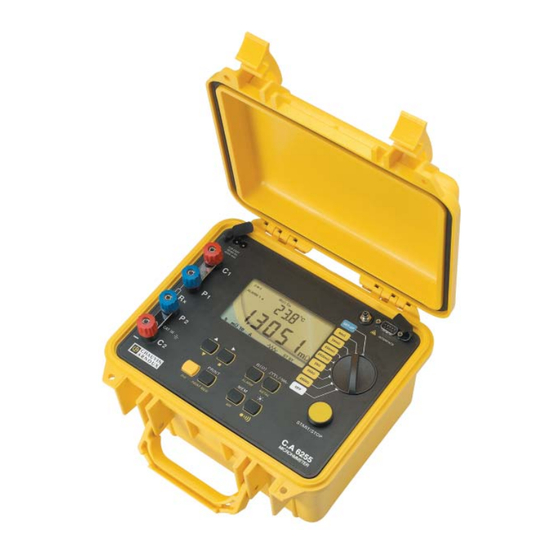
2. PRESENTATION The C.A 6255 microhmmeter is a top-quality portable digital measuring instrument with backlit LCD display. It is designed to measure very small resistances. Housed in a rugged construction-site type case with cover, the C.A 6250 is a self-contained instrument powered by a rechargeable battery with built-in charger. -
Page 6: Description
3. DESCRIPTION 3.1. FRONT PANEL OF THE C.A 6255 4 4mm-dia. safety terminals identifi ed as C1, P1, P2 and C2 9-way rotary switch: : instrument power off / setting for charging 2500 : 2500,0 range – measuring current 1 mA 250 ... -
Page 7: Display Unit
3.3. DISPLAY UNIT Dual liquid crystal display. Secondary display unit: measurement parameters / memory address Main display unit: measured values Other indications and symbols: indicates that the buzzer/audible signal is activated indicates the battery charge condition indicates that temperature compensation is activated indicates the metal selected for the temperature compensation function indicates that data are being transmitted to the serial interface Indicates the memory use level... -
Page 8: Rs 232 Interface: Characteristics
3.4. RS 232 INTERFACE: CHARACTERISTICS The RS 232 jack can be used with 4 different peripherals (choice of 4 different links in SET-UP) : - PC : activate RS232 link between the instrument and a computer - PRNT : activate RS232 link between the instrument and a printer - TRIG : activate the remote measurement triggering function... -
Page 9: Selection Of The Measurement Mode : Key
4.2. SELECTION OF THE MEASUREMENT MODE : There are three measurement modes: Inductive resistance measurement: Non-inductive resistance measurement: Non-inductive resistance measurement with automatic triggering: AUTO The measurement mode is selected by successive presses on the key; the mode selected is displayed bellow, in the centre of the display unit. - Page 10 4.2.2. MEASUREMENT IN NON-INDUCTIVE RESISTANCE MODE This mode is used to measure contact resistances, bondings, and, generally, any resistance having a time constant shorter than a few milliseconds. The measurement is started by pressing START and stops automatically as soon as the measurement result is available. START must be pressed again to make another measurement.
-
Page 11: Temperature Compensation
4.3. TEMPERATURE COMPENSATION: ( 4.3.1. PRINCIPLE The metals used for the windings of certain components (e.g. the copper in transformers and motors) have large temperature coeffi cients (of the order of 0.4 %/°C for copper and aluminium). This makes resistance measurements strongly dependent on the temperature of the component. The “temperature compensation”... -
Page 12: Storing And Retrieving Measurements (Mem / Mr)
4.5. STORING AND RETRIEVING MEASUREMENTS (MEM / MR) 4.5.1. STORING RESULTS (MEM) Measurement results can be stored at memory addresses identifi ed by an object number (OBJ) and a test number (TEST). An object is a “box” in which 99 tests can be stored. An object can thus represent a device on which a number of measurements/ tests are to be performed. -
Page 13: Instrument Configuration : Set-Up
4.6. INSTRUMENT CONFIGURATION : SET-UP This function is used to confi gure the instrument and change its confi guration as needed. After the rotary switch is turned to SET-UP : all segments of the display unit light for 1 second, SEt then appears on the small display unit to prompt for a key press, the ... -
Page 14: Printing Results (Print/Print Mem)
Value Changing of values Prnt / OFF / tri9 / PC / ut100 - type of communication: successive presses on - speed regulation: then + rate: Low / hight or OFF - successive presses on Fr / 9b - press on ... -
Page 15: List Of Coded Errors
4.7.1. IMMEDIATE PRINTING OF A MEASUREMENT (PRINT) Following a measurement or after the MR (memory retrieval) mode is accessed, the PRINT function can be used to print the measurement results. When the key is activated, the measurement is printed, along with the measurement conditions and R() if the function was activated). To stop printing, change the setting of the rotary switch. -
Page 16: Characteristics
5. CHARACTERISTICS 5.1. CHARACTERISTICS Remark: accuracies are stated in the form ± (n% read + C) where read = reading and C = a Constant, in practical units. They apply to the instrument placed in the reference conditions (see § 5.3), after 1 hour of warming up. ... -
Page 17: Environmental Conditions
5.3. ENVIRONMENTAL CONDITIONS Reference domain: 23°C ±5°C 45°C to 75 % HR. Nominal operating domain: 0°C to +50°C 20% to 80% HR without condensation. Extreme domain: -10°C to +55°C 10°C to +80°C, without condesation. Extreme storage and transport domain: -40°C to +60°C -15°C to +50°C, with battery charged. -
Page 18: Maintenance
Important remarks: Changing the battery causes stored data to be lost. Avoid storing the instrument with the battery charge too low. If the instrument is left unused for a long time (more than 2 months), the charging time will be longer. Before using the instrument again, it is therefore best to carry out 3 complete charging/discharging cycles. - Page 19 France: to our COFRAC-accredited metrology laboratories or to a Manumesure agency - outside mainland France: to a Chauvin Arnoux subsidiary or to the dealer who sold you this equipment. or make the adjustment using the procedure below, which requires equipment at least as effective as that used for the check performed previously.
-
Page 20: Warranty
6.2.2. UPDATING THE INTERNAL SOFTWARE If there are upgrades of the instrument, the updates of the internal software will be available on Chauvin Arnoux’s Web site: http://www.chauvin-arnoux.com with the procedure to be followed. The update will be performed using the UP9 command of the SEt maintenance menu. Once this command has been validated, 5 lines appear, indicating that the instrument is ready to communicate with the computer for the downloading of the new version of the program. - Page 21 FRANCE INTERNATIONAL Chauvin Arnoux Group Chauvin Arnoux Group 190, rue Championnet Tél : +33 1 44 85 44 38 75876 PARIS Cedex 18 Fax : +33 1 46 27 95 69 Tél : +33 1 44 85 44 85 Fax : +33 1 46 27 73 89 Our international contacts info@chauvin-arnoux.com...
Need help?
Do you have a question about the C.A 6255 and is the answer not in the manual?
Questions and answers