Chauvin Arnoux C.A. 6505 User Manual
Megohmmeter
Hide thumbs
Also See for C.A. 6505:
- User manual (148 pages) ,
- User manual (24 pages) ,
- User manual (72 pages)
Table of Contents
Advertisement
Quick Links
Advertisement
Table of Contents

Subscribe to Our Youtube Channel
Related Manuals for Chauvin Arnoux C.A. 6505


Summary of Contents for Chauvin Arnoux C.A. 6505
- Page 1 GB - User’s manual C.A 6505 Megohmmeter...
- Page 2 Thank you for purchasing a C.A. 6505 megohmmeter. To obtain the best service from your instrument: „ read this user manual carefully, „ comply with the precautions for use. WARNING, risk of DANGER! The operator must refer to this user’s manual whenever this danger symbol appears.
-
Page 3: Table Of Contents
CONTENTS 1. FIRST-TIME USE ..................................4 1.1. Unpacking ..................................4 1.2. Battery charge ................................4 2. DESCRIPTION ..................................5 2.1. Functions of the instrument ............................6 2.2. Switch ..................................... 6 2.3. Keys and button ................................6 2.4. Display .................................... 7 3. -
Page 4: First-Time Use
1. FIRST-TIME USE 1.1. UNPACKING Œ ’ ‘ Ž ➀ One carrying bag. Two 2 m safety leads with a high-voltage plug at each end (one red and one blue). ➁ One 2 m guarded safety lead with a high-voltage plug at one end and a high-voltage plug with rear pick-up jack at the ➂... -
Page 5: Description
2. DESCRIPTION... -
Page 6: Functions Of The Instrument
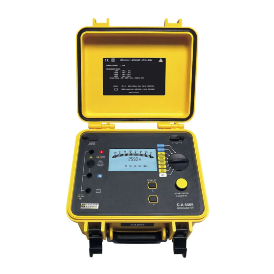
2.1. FUNCTIONS OF THE INSTRUMENT The C.A 6505 megohmmeter is a portable instrument housed in a rugged field case with lid and operates on either battery or line power. It makes voltage, insulation, and capacitance measurements. This instrument contributes to the safety of electrical installations and equipment. It has many advantages, for example: „... -
Page 7: Display
2.4. DISPLAY min sec µA µF 2.4.1. DIGITAL DISPLAY The main digital display indicates the values for insulation measurement: resistance, DAR PI, DD or capacity. The small digital display unit indicates the test voltage applied by the instrument or the voltage measured on the object tested. During the insulation measurement, it indicates the elapsed time or the test voltage. -
Page 8: Measurement Functions
3. MEASUREMENT FUNCTIONS 3.1. VOLTAGE MEASUREMENT As soon as the switch is set to an insulation measurement position, the instrument automatically measures the presence of any AC/DC voltage. This voltage is measured at all times and indicated on the small display unit. The instrument automatically determines AC or DC: the AC measurement is an RMS value If an excessively high external voltage is present on the terminals (>... - Page 9 Once the connections have been made, choose the When powered up, the instrument displays the test voltage on the rotary switch. condition of the battery, 1000V 1000V Ω 4T Ω the test voltage, then the voltage present on the object to be tested. Press the START/STOP key to start the measurement.
-
Page 10: Measurement Of The Pi
3.3. MEASUREMENT OF THE PI Set the switch to one of the insulation measurement Start the measurement by a long press on the START/ positions. STOP key. The long press is acknowledged by an audible beep. > 2s 1000V 1000V Ω... -
Page 11: Adjustment Of The Variable Test Voltage
The quality of the insulation is a function of the results found. Condition of the insulation < 1 Inadequate or even < 1.25 dangerous < 2 < 1.6 < 4 Good > 1.6 > 4 Excellent 3.4. ADJUSTMENT OF THE VARIABLE TEST VOLTAGE This function makes it possible to use test voltages other than the 4 available. -
Page 12: Error Messages
The maximum test voltage value is retained in a non-volatile memory. It will be displayed for a few seconds on selection of an affected range. For example, if the maximum voltage is 750 V, it will be applied and displayed on all settings of the switch from 1000 V up. 3.6. -
Page 13: Complementary Functions
4. COMPLEMENTARY FUNCTIONS 4.1. ADJUSTMENTS OF THE PI It is possible to modify the PI times to meet specific needs. This function is not readily accessible because it is not often used. Reminder: PI = R 10 min / 1 min The first PI time is 1 mn. -
Page 14: Internal Software Version
4.3. INTERNAL SOFTWARE VERSION To view the internal software version of the instrument, keep the DISPLAY key pressed and turn the switch to the 1000 V position. 1000V 1000V 4T Ω Ω DISPLAY... -
Page 15: Specifications
5. SPECIFICATIONS 5.1. REFERENCE CONDITIONS Influence quantities Reference values Temperature 23 ± 3°C Relative humidity 45 to 55% RH Supply voltage 9 to 12 V Frequency range DC and 15.3...65 Hz Capacity in parallel on resistor 0 µF Electrical field Magnetic field <... - Page 16 „ Accuracy Test voltage 500 V - 1000 V - 2500 V - 5000 V Specified measurement 10 - 999 kΩ 4.00 - 39.99 MΩ 40.0 - 399.9 MΩ 0.400 - 3.999 GΩ range 1.000 - 3.999 MΩ Resolution 1 kΩ 10 kΩ...
- Page 17 „ Typical change curve for test voltages according to load Range 500 V MΩ 0,01 Range 1000 V 1200 1000 MΩ 0,01 Range 2500 V 3000 2500 2000 1500 1000 MΩ 0,01 Range 5000 V 6000 5000 4000 3000 2000 1000 MΩ...
-
Page 18: Power Supply
5.2.4. CAPACITANCE This measurement is made at the end of each insulation measurement, while the circuit is being discharged. Specified measurement range 0.001 - 9.999 µF 10.00 - 49.99 µF Resolution 1 nF 10 nF Accuracy 10% ± 1 pt 5.3. -
Page 19: Compliance With International Standards
Diagram of climatic conditions: % RH °C -50 -40 -30 -20 -10 0 10 20 30 40 50 60 70 80 90 1: Reference range 2: Operating range 3: Storage range (without battery) 5.6. COMPLIANCE WITH INTERNATIONAL STANDARDS „ Electrical safety as per: IEC 61010-1 and IEC 61557 „... -
Page 20: Maintenance
„ bAt on the small display unit and chrG flashing on the main display unit means that slow charging is in progress „ bAt on the small display unit and FULL on the main display unit means that charging is over. The battery must be replaced by Manumesure or by a repairer approved by CHAUVIN ARNOUX. 6.2. REPLACEMENT OF THE FUSE If FUSE -G- appears on the display. -
Page 21: Warranty
7. WARRANTY Except as otherwise stated, our warranty is valid for 24 months starting from the date on which the equipment was sold. Extract from our General Conditions of Sale provided on request. The warranty does not apply in the following cases: „... -
Page 22: Glossary
8. GLOSSARY This glossary lists the terms and abbreviations used in this document and on the digital display unit of the instrument. Battery charge condition Dielectric Absorption Ratio. DAR = R 1 min / 30 s Maximum test voltage that will be applied during the measurement Polarisation Index. -
Page 23: Delivery Condition
9. DELIVERY CONDITION C.A 6505 Megohmmeter Delivered with a carrying bag containing: „ Two 2 m safety leads with a HV plug at each end (one red and one blue). „ One 2 m guarded safety lead with a HV plug at one end and a HV plug with a rear pick-up jack at the other end (black). „... - Page 24 FRANCE INTERNATIONAL Chauvin Arnoux Group Chauvin Arnoux Group 190, rue Championnet Tél : +33 1 44 85 44 38 75876 PARIS Cedex 18 Fax : +33 1 46 27 95 69 Tél : +33 1 44 85 44 85 Fax : +33 1 46 27 73 89 Our international contacts info@chauvin-arnoux.com...
Need help?
Do you have a question about the C.A. 6505 and is the answer not in the manual?
Questions and answers