Table of Contents
Advertisement
Quick Links
Advertisement
Table of Contents

Related Manuals for Chauvin Arnoux C.A 6456


Summary of Contents for Chauvin Arnoux C.A 6456
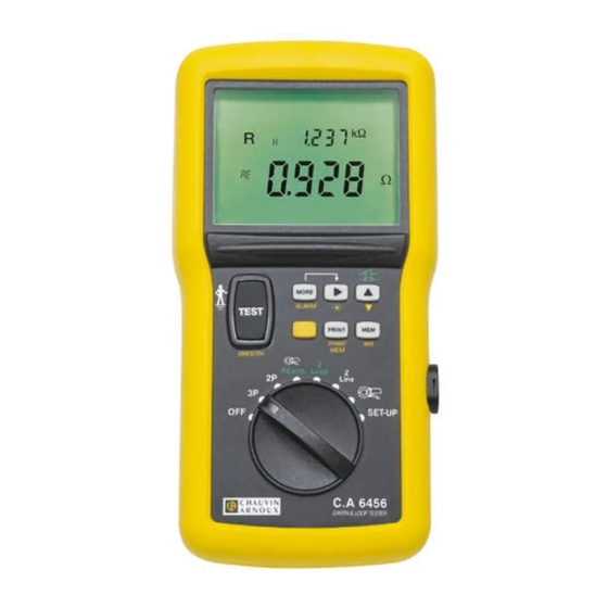
- Page 1 Loop and earth Ohmmeter C.A 6456 E N G L I S H User's manual...
- Page 2 Category III meets the reliability and availability requirements of uses on fixed industrial installations (cf. EN 61010-1 + A2). I Never use the C.A 6456 tester on installations having a potential greater than 550V with respect to earth.
-
Page 3: Table Of Contents
SOMMAIRE PRESENTATION ........................4 Environmental conditions ......................5 Compliance with standards ......................5 Power supply ..........................5 DESCRIPTION ......................... 6 GENERAL USE ........................9 Automatic checks ........................9 Instrument configuration (SET-UP) ..................10 Compensation of the leads ...................... 11 Recording measurement results (MEM) .................. 13 Recalling recorded values (MR) .................... -
Page 4: Presentation
1. PRESENTATION Portable instrument for testing and checking the safety of new and existing electrical installations (loop ohmmeter). Measurement functions :- Voltage, - Frequency, - Test of protective conductor, PE, - Earth resistance with 2 auxiliary rods (3P method) - Coupling resistance (2P method) - Loop impedance, with display of the resistive part and of the inductive part, - Calculation of short-circuit currents, - Current, with clamp,... -
Page 5: Environmental Conditions
position of the phase conductor 12 "object" number for storage auxiliary earth rod detected 13 main display unit A1 measurement without triggering of residual current differentials measurement smoothed for display (RCD) (low power signal) audible buzzer activated 15 measurement with triggering of RCD (full power level) communication in progress (serial link) 16 alarm function activated or display of an alarm threshold battery charge level... -
Page 6: Description
2. DESCRIPTION Preliminary remarks : Several types of action are possible on each key of the keypad, depending on whether the user presses the key briefly (short press, < 2s, validated by a beep) or at length (long press, > 2s, validated by a beep having a tone different from that of the beep emitted for a short press). - Page 7 8 WAY ROTARY SWITCH : - OFF : instrument off - 3P : earth measurement with 2 auxiliary rods - 2P : AC or earth coupling resistance measurement - REARTH / earth measurement in a live condition, with one auxiliary rod (selective earth if clamp connected) - ZLOOP : loop impedance measurement with 3 wires (high or low current), between...
- Page 8 => select the memory block (OBJ) or line (TEST) for storage, retrieval on screen, or printing PRINT PRINT MEM => switch the backlighting of the display unit on/off with switch ZLOOP and/or ZLINE: => select the type of measurement ("tripping" "non-tripping"...
-
Page 9: General Use
BACKLIT LCD DISPLAY UNIT OPTICAL SERIAL COMMUNICATION INTERFACE SAFETY INPUT TERMINALS , dia. 4mm, marked L, N, PE and P (terminal used for earth measurements in a live condition). maximum voltage with respect to earth = 550 V MARKED SOCKET FOR THE CONNECTION OF A CURRENT CLAMP 3. -
Page 10: Instrument Configuration (Set-Up)
3.1.3 MEASUREMENT CONDITIONS CHECK or a measurement to be authorized, in addition to the above two checks (determination of the position of the phase and of the voltage of the PE conductor), the following conditions must be satisfied: and U <... -
Page 11: Compensation Of The Leads
Parameter Default Presses Values values Erase memory (totally or partially) see §3.6 voltage Reference voltage for the MORE see § 4.3.2 measured calculation of I 6.9 or 12 mA Value of the low current I TEST MORE 12 mA in "non-tripping" measurement see §... - Page 12 3.3.1 APPLYING A COMPENSATION Set the switch to one the LOOP/RCD positions. Connect one end of the three-conductor cord terminated by 3 leads to the device. Short-circuit the 3 leads. In the case of a mains outlet, connect the two earth pins with the earth pins with leads. Perform a long press on the TEST button.
-
Page 13: Recording Measurement Results (Mem)
RECORDING MEASUREMENT RESULTS (MEM) IMPORTANT - Each measurement stored in the instrument is identified by 2 indices: an OBJ no. and a TEST no.; a given object (OBJ) generally contains several TEST nos. For example: an OBJ no. can be used to locate an installation, and the TEST nos. identify the various measurements made on this installation. -
Page 14: Erasing Recorded Values
ERASING RECORDED VALUES The memory of the instrument can be erased, totally or partially, in the SET-UP rotary switch position: Complete Erasure of a memory block Erasure of a memory line erasure of the (OBJ) (TEST) memory PUSH PUSH PUSH 02 07 02 07 OBJ TEST... -
Page 15: Printing Measurement Results (Print)
PRINTING MEASUREMENT RESULTS (PRINT) PRINT : print the measurement made and all of the parameters attached to it. Examples of printing tickets: Remark : In the SET-UP position, pressing the PRINT key triggers printing of the configuration of the instrument. PRINTING RECORDED VALUES (PRINT MEM) Recorded values can be printed with the switch in any position except SET-UP or OFF. -
Page 16: Measurements
4. MEASUREMENTS VOLTAGE MEASUREMENT 4.1.1 DESCRIPTION OF THE FUNCTION Voltage measurement is accessible with the switch in any position except SET-UP or OFF. 4.1.2 PREPARATION OF THE MEASUREMENT (CONNECTION) => Switch the instrument on => Connect the instrument to the installation using the measuring cable terminated by a mains plug, =>... - Page 17 Parameters accessible in the REarth setting: Initial display MORE MORE press) press) A ALARM ∆ ∆ ∆ ∆ ∆ L Initial display ---- press) A ALARM ∆ ∆ ∆ ∆ ∆ PE ---- A ALARM ∆ ∆ ∆ ∆ ∆ N press) ---- ----...
- Page 18 Parameters accessible in the current measurement setting: MORE MORE Initial display press) press) ---- Initial dispaly ALARM ---- press) ALARM ---- press) ALARM Pressing the key once more returns to the initial display. MORE 4.1.5 CHARACTERISTICS 4.1.5.1 Measurement ranges and accuracy Frequency : the value displayed is guaranteed only for a voltage 10 VRMS (all settings of the switch...
- Page 19 4.1.5.2 Influencing conditions Variation of the measurement Influencing Limits of the domain quanstities Typical Maximum of use Temperature 1 %/10 °C ± 1pt 2 %/10 °C + 2pt -10 to + 55 °C Relative humidity 10 to 85 % HR at 45°C 3 % + 2 pt POwer supply voltage 6.8 to 10 V...
- Page 20 4.1.6 WARNINGS OR ERROR REPORTS Preliminary remark: The complete list of coded errors is given in § 7. Display - Indication Remark - Possible cause(s) One of the voltages measured (U , or U > 550V is > 550V. <15.3Hz (or) >65Hz Frequency outside measurement domain or 450Hz (depends on type of measurement)
-
Page 21: And 3P Earth Measurement
2P AND 3P EARTH MEASUREMENT 4.2.1 DESCRIPTION OF THE FUNCTION 3P and 2P earth measurements are made in a power-off condition. The measurements are made with two auxiliary rods (3 poles) and one auxiliary rod (2 poles), respectively. Note however that measurements with 2 auxiliary rods are more accurate. Measurement in 3P mode: the instrument generates an alternating current square wave (128 Hz) between terminals H and E, then measures the voltage between terminals S and E: from this voltage and the current generated, it deduces global earthing resistance R... - Page 22 => Cut off power to the installation and disconnect the earth of the installation => Set the switch to 2P or 3P. => Then connect the measuring cables to the instrument and to the rods, complying with the following distances and connections (example of connection for 3P measurement). Remark : to be sure that rod S is located in a zone that is not influenced by other earth electrodes, move it ( 10% of the distance and repeat the measurement.
- Page 23 Parameters accessible in the 3P setting : MORE MORE MORE Initial display press) press) press) Initial display E ALARM ∆E ------- E ALARM ∆E ------- Pressing the key once more causes a return to the initial display. MORE 4.2.5 CHARACTERISTICS 4.2.5.1 MEASUREMENT RANGES AND ACCURACY Particular reference : resistance of auxiliary earths <...
- Page 24 4.2.5.2 Influencing conditions Variation of the measurement Limits of the domain Influencing quantities of use Typical Maxim um Temperature -10 to + 55 °C 1% /10 ° C ± 1pt 2% /10 ° C + 2pt Relative humidity 10 to 85% RH at 45°C 3% + 2 pt Power supply voltage 6.8 to 10 V...
-
Page 25: Earth Measurement In Live Condition (Rearth)
EARTH MEASUREMENT IN LIVE CONDITION (REARTH) 4.3.1 DESCRIPTION OF THE FUNCTION This measurement is made with a single auxiliary rod (voltage probe) connected to terminal (P), yielding a saving of time with respect to a conventional measurement with 2 auxiliary rods. A specific additional current clamp is necessary to make a selective earth measurement. - Page 26 the current generated for the measurement at low current : PUSH MORE 12 mA ∆ ∆ ∆ ∆ ∆ n Selection of current MORE twice to exit from programming PUSH The type of compensation of the measuring cables (see § 3.3) the alarm threshold Z or R the number of measurements to be counted to smooth the measurement (see §...
- Page 27 Case of an installation with a TN type neutral situation (selective measurement) : => Connect the mains socket (or the 3 separate cables) to the installation to be tested, => Connect a current probe to the terminal and encircle the earth of which the resistance is to be measured: the current used to calculate Z is that measured...
- Page 28 Parameters accessible in earth measurement in live condition, mode (high current): Initial display MORE MORE MORE MORE press) press) press) press) A ALARM Initial display ∆ ∆ ∆ ∆ ∆ L A ALARM ∆ ∆ ∆ ∆ ∆ PE press) ∆...
- Page 29 4.3.5 CHARACTERISTICS 4.3.5.1 Measurement ranges and accuracy Particular reference conditions : nominal voltage of the installation = 90 to 550 V, nominal frequency of use = 15.3 to 65 Hz, resistance in series with voltage probe: < 100 Ω inductive part < 0.1 x the resistive part of the impedance measured, resistance of the cable connected to terminal PE corrected, contact voltage <...
- Page 30 Characteristic in "selective" mode: Charge duration : 300 µs cycle Display range 400 Ω 4000 Ω Specified measurement 0.5 - 1.9 Ω 2.0 - 19.9 Ω 20.0 - 399.9 Ω 400 - 3999 Ω domain Peak measuring ≥ 30 mA ≥...
- Page 31 4.3.6 WARNINGS OR ERROR REPORTS (EARTH MEASUREMENT IN LIVE CONDITION) Preliminary remark: The complete list of coded errors is given in § 7. Indication Cause possible between the TEST key and PE: the measurement Voltage > U is disabled. > 25 (or) 50V One of the voltages, U or U is <...
-
Page 32: 3-Wire Loop Measurement (Z Loop)
Note that the instrument allows measurement of loop impedance LPE behind 30mA circuit-breakers without causing them to trip (principle patented by Chauvin Arnoux). In an IT network, use the instrument's "ZLINE" function. The measurement principle is the same as for an earth measurement in a live condition. - Page 33 4.4.2 PREPARATION FOR THE MEASUREMENT (CONNECTION)) => If necessary, in SET-UP mode: - set threshold voltage U (see § 3.2), - the type of compensation of the measuring cables (see § 3.3)) - set the alarm threshold Z or R (see §...
- Page 34 => Compensate the measuring cables (see § 3.3), => Select the measuring current: press => high ( ) for a greater accuracy: - if no tripping of a earth fault breaker is foreseen (measurement made upstream of the RCDs), - if the earth fault breaker concerned is short-circuited for greater accuracy, =>...
-
Page 35: 2-Wire Loop Measurement (Z Line)
Characteristics of calculation of short-circuit current I Display range 400 A 4000 A 40 kA Resolution 0.1 A 10 A Accuracy Resistances, impedances : Accuracy values indicated for earth measurements in a live condition (see § 4.2.5) Short-circuit current : Accuracy of impedances + accuracy of measuremnt of voltage U , if it is used Calculation formula... - Page 36 4.5.3 MEASUREMENT PROCEDURE In the case of 2-wire loop measurements, there is no monitoring of the potential of terminal PE nor the installation PE line. Loop measurements with 2 wires are identical to loop measurements with 3 wires except as follows : - the voltage between the TEST key and PE is not measured: only the potential between terminals L and N is measured;...
-
Page 37: Current Measurement ( )
CURRENT MEASUREMENT ( 4.6.1 DESCRIPTION OF THE FUNCTION , position, the instrument measures the alternating current continuously, without the TEST key In the being pressed. The instrument deduces the current flowing in the cable(s) clamped by the probe according to the transformation ratio of the probe. - Page 38 4.6.5 CHARACTERISTICS 4.6.5.1 Measurement ranges and accuracy Particular reference conditions : - peak factor = 1.414, - DC component < 0.1 %, - operating frequency domain = 15.3 to 450 Hz. Characteristics with an MN 20 current probe : Display range 400 mA 40 A Specified measurement domain...
-
Page 39: Glossary
5. GLOSSARY frequency of the signal current current threshold ALARM short-circuit current between terminals L and N, L and PE, N and PE KLPE KNPE current flowing in the current probe during a selective earth measurement in a live condition. inductive part of Z inductive part of impedance Z global compensation between 2 terminals (2P and ZLine) -
Page 40: Maintenance
Like all measuring or testing devices, the instrument must checked regulary. This instrument should be checked at least once a year. For checking and calibration, contact one of our accredited metrology laboratories (information and contact details available on request), at our Chauvin Arnoux subsidiary or the branch in your country. -
Page 41: List Of Coded Errors
Er24 Backup memory full (action: delete stored data) 8. TO ORDER C.A 6456 earth and loop tester P01123512 Delivered in a carrying bag containing: - 1 measuring cable for Euro mains socket, - 1 measuring cable, 3 separate leads,... - Page 42 07 - 2013 Code 689909B02 - Ed. 2 DEUTSCHLAND Chauvin-Arnoux GmbH SCHWEIZ - Chauvin-Arnoux AG Straßburger Str. 34 - 77694 Kehl / Rhein Moosacherstrasse 8804 Tél : 7851 99 26-0 - Fax : 7851 99 26-60 Tél : 44 727 75 55 - Fax : 44 727 75 56 ESPAÑA Chauvin-Arnoux Ibérica...
Need help?
Do you have a question about the C.A 6456 and is the answer not in the manual?
Questions and answers