Chauvin Arnoux C.A 6545 User Manual
Megohmmeters
Hide thumbs
Also See for C.A 6545:
- User manual (162 pages) ,
- User manual (108 pages) ,
- User manual (24 pages)
Table of Contents
Advertisement
Quick Links
Advertisement
Table of Contents

Related Manuals for Chauvin Arnoux C.A 6545


Summary of Contents for Chauvin Arnoux C.A 6545
- Page 1 C.A 6545 Mégohmmètres Megohmmeters Megohmmeter C.A 6547 Megaohmmetri Megaóhmetros F R A N Ç A I S Notice de fonctionnement E N G L I S H User's manual D E U T S C H Bedienungsanleitung I T A L I A N O Libretto d’Istruzioni...
- Page 2 English Meaning of symbol Caution! Please consult the User Manual before using the device. In this User Manual, failure to follow or carry out instructions preceded by this symbol may result in personal injury or damage to the device and the installations. Meaning of symbol This appliance is protected by double insulation or reinforced insulation.
-
Page 3: Table Of Contents
CONTENTS 1. PRESENTATION ..........................35 1.1 The megohmmeters ......................35 1.2 The accessories ........................35 2. DESCRIPTION ..........................36 Casing ............................ 36 Display ........................... 37 3. MEASUREMENT FUNCTIONS ....................39 AC / DC voltage ........................39 3.2 Insulation measurements ...................... 39 4. -
Page 4: Presentation
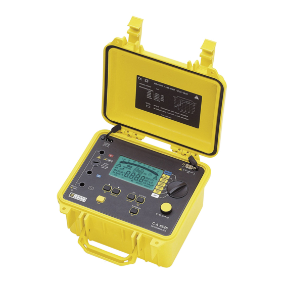
1. PRESENTATION The megohmmeters The C.A 6545 and C.A 6547 megohmmeters are portable units, fitted into a rugged construction site casing with cover, operating on battery and on AC current. They are used to measure: voltages: insulation, capacity. These megohmmeters help to ensure the safety of electrical installations and equipment. -
Page 5: Description
SET-UP: adjustment of unit configuration 1 yellow START / STOP push button: start / end of measurement 6 keys (C.A 6545) or 8 keys (C.A 6547) made of elastomer each having a main function and a secondary function: Selection of the second function (in yellow Italics above each key) -
Page 6: Display
Socket for connection to AC network (direct operation on AC network/battery recharge) Male connector RS 232 series INTERFACE (9-pin) for connection to a PC or printer (C.A 6547 only). On the C.A 6545, this connector is used for adjustments of the instrument only. Note: The battery compartment is inside the casing. - Page 7 2.2.1 Digital display. The main digital display indicates the values for insulation measurement: resistance, DAR PI, DD or capacity). The small digital display indicates the voltage measured or applied by the instrument. During the insulation measurement, the elapsed time or voltage is displayed.
-
Page 8: Measurement Functions
3. MEASUREMENT FUNCTIONS AC / DC voltage Any rotation of the switch on an insulation position sets the unit to automatic AC / DC voltage measurement. The voltage is measured continuously and indicated on the small display. The start of the insulation measurements is inhibited if an excessively high external voltage is present on the terminals, before pressing START. - Page 9 If the measurements are unstable, it is possible to use the SMOOTH function (see § 4.5). Pressing on a V-TIME key during the measurement alternatively displays the measurement time and the exact voltage generated on the small display (see § 4.2). The stopping of the measurement is caused by pressing the STOP key.
-
Page 10: Special Functions
4. SPECIAL FUNCTIONS This key is used to select the secondary function of the function keys. It is always related to the symbol. This symbol disappears as soon as the selected function key is pressed, unless the key is activated. In this case, it disappears only if the key is pressed again or if other function keys are pressed. - Page 11 Then the PI or DAR ratios are calculated: PI* = R (2 values to be noted during a 10-min. measurement) 10 min / 1 min DAR = R (2 values to be noted during a 1-min. measurement) 1 min / 30 s The quality of the insulation is a function of the results.
- Page 12 Automatic DAR or PI measurement: If the R-DAR-PI-DD key is actuated during the voltage measurement before the start of a measurement, the display is as follows: → → → - - - - MΩ DAR - - - - PI - - - - DD - - - - ↑...
-
Page 13: Alarm Key
PC. On the C.A 6545, during measurement, up to 20 samples may be recorded in the unit at the rate chosen in the SET-UP (the default value being 30 seconds). -
Page 14: Key
Secondary SMOOTH function Used to activate a digital filter for insulation measurements. It affects only the display (which is smoothed) and not the measurements. This function is useful in case of high instability of the displayed insulation values, caused by a strong capacitive component of the part to be tested, for example. - Page 15 Parameters Control Display to be modified main small symbols values Test duration of the test, in tESt 30 : 00 min. sec, 01:00 - 59:59 "Programmed-time test" mode and 2 time for second period first period min.: sec 00:30 - 59:59 R-DAR-PI-DD PI calculation (10:00)
- Page 16 4.7.1 Memory deletion In the SET-UP, press the MEM key: - The MEM symbol flashes - ALL is shown flashing on the small display - The main display indicates cLR To delete the entire memory, press again on the MEM key for 2 seconds: - The MEM symbol is displayed steady.
- Page 17 4.7.5 Automatic measuring range In the SET-UP, 6 press on the key: - The small display indicates rAnG - The main display indicates Auto Use the key to choose a fixed (1, 2 or 3 on the main display) or automatic (Auto on the main display) measurement range Note: The fixed measurement ranges correspond to the current ranges of the following measurements: 1 : 50 pA to 200 nA...
-
Page 18: Use
5. USE Measurement procedure Start up the instrument by setting the switch to the corresponding position. All the segments of the LCD screen are displayed, then the battery voltage. Connect the + and - leads to the measurement points. The voltage is measured continuously and indicated on the small display. If an external voltage higher than the authorised limit value (see §... -
Page 19: Capacity Measurement
Connection diagram for measurement of low insulation (example: motor) Connection diagram for measurement of strong insulation a) Example of a motor (reduction of capacitive effects) b) Example of a cable (reduction of superficial leak effects) External insulator Insulator Braid Cable Guard Capacity measurement Capacity measurement is performed automatically during the insulation measurement, and is displayed... -
Page 20: Memory / Rs 232 (C.a 6547)
6. MEMORY / RS 232 (C.A 6547) RS 232 Characteristics The speed in bauds may be adjusted to 300, 600, 1200, 2400, 4800, 9600, or «Parallel» for printing on parallel printers via the optional series/parallel adapter. This adjustment is performed in the SET-UP menu (see § 4.7.2) Data format: 8 data bits, 1 stop bit, no parity, protocol Xon / Xoff Connection to serial printer Front view... -
Page 21: Recording/Reviewing Of Memorised Values (Mem/Mr Key)
Recording/reviewing of memorised values (MEM/ MR key) 6.2.1 Primary MEM function (memorisation) This function is used to record results in the device’s RAM. These results are recordable at an address identified by an object number (OBJ) and a test number (TEST). -
Page 22: Printing Measured Values (Print/Print Mem Key) (C.a 6547)
To stop printing, change the position of the rotary switch. Depending on the function used, the following models are obtained. Insulation Measurements CHAUVIN ARNOUX C.A 6547 Instrument number: 000 001 INSULATION RESISTANCE TEST PURPOSE: 01 TEST: 01 (printed only in MR mode) Description: .......... - Page 23 To start printing, press again on the PRINT key. To stop printing, change the position of the rotary switch. The printing of each data group is reduced to the main results. Example: CHAUVIN ARNOUX C.A 6547 Instrument number: 000 001 INSULATION RESISTANCE TEST PURPOSE: 01 TEST: 01 Description: ..........
-
Page 24: Printing With Series-Parallel Adapter
INSULATION RESISTANCE TEST PURPOSE: 01 TEST: Description: ........................Date: .......... 31.03.1998 Starting time: ........15h 10 Running time: ......15 min 30 sec Temperature: ......°C ..°F Relative humidity: ........% Test voltage: ........1000 V Insulation resistance (R): ....385 GΩ DAR: ............ -
Page 25: Specifications
7. SPECIFICATIONS Reference conditions Influence quantities Reference values Temperature 23°C ± 3 K Relative humidity 45% to 55 % Supply voltage 9 to 12 V Frequency range DC and 15.3...65 Hz Capacity in parallel on resistor 0 µF Electrical field Magnetic field <... - Page 26 Resistance range in voltage mode Variable voltage (V) Accuracy Test 500 V 500 V - 1000 V 500 V - 1000 V - 2500 V - 5000 V voltage Specified 300…999 kΩ measurement 30...99 kΩ 100...299 kΩ 4.00...39.99 MΩ 40.0...399.9 MΩ range 1.000...3.999 kΩ...
- Page 27 Typical build-up time for the measurement according to components tested (U = 0,03 dist These values include the influences caused by the charge of the capacitive component, by the automatic range system and to the test voltage control Test voltage Load Non capacitive With capacitance of 1 µF...
- Page 28 Range 2500 V 3000 2500 2000 1500 1000 Range 5000 V 6000 5000 4000 3000 2000 1000 Capacity measurement (after discharge of tested component) Specified measurement range 0.005...9.999 µF 10.00...49.99 µF Resolution 1 nF 10 nF Accuracy 10% reading +1 pt Leak current measurement Range of 0,000...
-
Page 29: Power Supply
Supposing a DAR measurement of 1 minute, 10 times per day, with a PI measurement of 10 minutes, 5 times per day, l’autonomie sera d’environ 15 jours ouvrables ou 3 semaines. Recharge time (C.A 6545 and C.A 6547) 6 hours to recover 100% capacity (10 hours if the battery is completely run down) 0.5 hours to recover 10% capacity (charge life: 2 days approximately) -
Page 30: Variations In Operating Range
7.6.1. Electromagnetic compatibility: NF EN 61326-1 (Ed. 97) + A1, industrial environment category 7.6.2. Mechanical protection IP 53 per NF EN 60529 (Ed. 92) IK 04 (per NF EN 50102 Ed. 95) Variations in operating range Influential Range Quantity Influence quantity of influence influenced (1) -
Page 31: Maintenance
If the unit is activated and the batteries have a voltage of > 8 V, normal utilisation of the unit is authorised. The battery should be replaced by Manumesure or by a repairer approved by CHAUVIN ARNOUX. Changing the battery entails the loss of memorised data. Pressing on the MEM / MR key then causes the display of «OFF». -
Page 32: Guarantee
Our guarantee is applicable for twelve months after the date on which the equipment is made available (extract from our General Conditions of Sale, available on request). 10. TO ORDER C.A 6545 ..........................P01.1397.01 C.A 6547 ..........................P01.1397.02 Delivered with bag containing:...
Need help?
Do you have a question about the C.A 6545 and is the answer not in the manual?
Questions and answers