Table of Contents
Advertisement
Available languages
Available languages
LOVATO ELECTRIC S.P.A.
24020 GORLE (BERGAMO) ITALIA
VIA DON E. MAZZA, 12
TEL. 035 4282111
FAX (Nazionale): 035 4282200
FAX (International): +39 035 4282400
L
E
E-mail info@
ovato
lectric.com
L
E
Web
www.
ovato
lectric.com
WARNING!
- Read the manual carefully before installation and use.
- These devices must be installed by qualified personnel, in compliance with current plant-engineering regulations, in order to avoid damage to persons or property.
- Before any maintenance operation on the device, switch off power supply from measuring and supply inputs.
- The manufacturer assumes no responsibility for electrical safety in the event of improper use of the device.
- The products described in this document are subject to updates or modifications at any time. Data and descriptions in the catalogue therefore do not have any contractual value.
- The building's electrical system must incorporate a switch or circuit breaker. It must be installed close to the equipment and within easy reach of the operator. It must be marked as the disconnecting device of the
equipment: IEC/ EN 61010-1 § 6.12.2.1.
- Clean the instrument with a soft cloth. Do not use abrasives, liquid detergents or solvents.
CONTENTS
Description . . . . . . . . . . . . . . . . . . . . . . . . . . . . . . . . . . . . . . . . . . . . . . . . . . . . . . . . . . . . . . . . . . . . . . . . . . . . . . . . . . . . . . . . . . . . . . . . . . . . . . . . . . . . . . . . . . . . . . . . . . . . . . . . . . . . . . . . . . . . . . . . . . . . . . . . . . . .
Front button functions . . . . . . . . . . . . . . . . . . . . . . . . . . . . . . . . . . . . . . . . . . . . . . . . . . . . . . . . . . . . . . . . . . . . . . . . . . . . . . . . . . . . . . . . . . . . . . . . . . . . . . . . . . . . . . . . . . . . . . . . . . . . . . . . . . . . . . . . . . . . . . . . . . . .
Front LEDs . . . . . . . . . . . . . . . . . . . . . . . . . . . . . . . . . . . . . . . . . . . . . . . . . . . . . . . . . . . . . . . . . . . . . . . . . . . . . . . . . . . . . . . . . . . . . . . . . . . . . . . . . . . . . . . . . . . . . . . . . . . . . . . . . . . . . . . . . . . . . . . . . . . . . . . . . . . . .
Display indications . . . . . . . . . . . . . . . . . . . . . . . . . . . . . . . . . . . . . . . . . . . . . . . . . . . . . . . . . . . . . . . . . . . . . . . . . . . . . . . . . . . . . . . . . . . . . . . . . . . . . . . . . . . . . . . . . . . . . . . . . . . . . . . . . . . . . . . . . . . . . . . . . . . . . . .
AUTOSET guided configuration . . . . . . . . . . . . . . . . . . . . . . . . . . . . . . . . . . . . . . . . . . . . . . . . . . . . . . . . . . . . . . . . . . . . . . . . . . . . . . . . . . . . . . . . . . . . . . . . . . . . . . . . . . . . . . . . . . . . . . . . . . . . . . . . . . . . . . . . . . . . .
Navigating the display pages . . . . . . . . . . . . . . . . . . . . . . . . . . . . . . . . . . . . . . . . . . . . . . . . . . . . . . . . . . . . . . . . . . . . . . . . . . . . . . . . . . . . . . . . . . . . . . . . . . . . . . . . . . . . . . . . . . . . . . . . . . . . . . . . . . . . . . . . . . . . . . .
Operational status . . . . . . . . . . . . . . . . . . . . . . . . . . . . . . . . . . . . . . . . . . . . . . . . . . . . . . . . . . . . . . . . . . . . . . . . . . . . . . . . . . . . . . . . . . . . . . . . . . . . . . . . . . . . . . . . . . . . . . . . . . . . . . . . . . . . . . . . . . . . . . . . . . . . . . . .
Remote display unit . . . . . . . . . . . . . . . . . . . . . . . . . . . . . . . . . . . . . . . . . . . . . . . . . . . . . . . . . . . . . . . . . . . . . . . . . . . . . . . . . . . . . . . . . . . . . . . . . . . . . . . . . . . . . . . . . . . . . . . . . . . . . . . . . . . . . . . . . . . . . . . . . . . . . .
Startup methods . . . . . . . . . . . . . . . . . . . . . . . . . . . . . . . . . . . . . . . . . . . . . . . . . . . . . . . . . . . . . . . . . . . . . . . . . . . . . . . . . . . . . . . . . . . . . . . . . . . . . . . . . . . . . . . . . . . . . . . . . . . . . . . . . . . . . . . . . . . . . . . . . . . . . . . . .
Protections . . . . . . . . . . . . . . . . . . . . . . . . . . . . . . . . . . . . . . . . . . . . . . . . . . . . . . . . . . . . . . . . . . . . . . . . . . . . . . . . . . . . . . . . . . . . . . . . . . . . . . . . . . . . . . . . . . . . . . . . . . . . . . . . . . . . . . . . . . . . . . . . . . . . . . . . . . . . .
Motor thermal protection . . . . . . . . . . . . . . . . . . . . . . . . . . . . . . . . . . . . . . . . . . . . . . . . . . . . . . . . . . . . . . . . . . . . . . . . . . . . . . . . . . . . . . . . . . . . . . . . . . . . . . . . . . . . . . . . . . . . . . . . . . . . . . . . . . . . . . . . . . . . . . . . . .
Motor thermal protection via PTC . . . . . . . . . . . . . . . . . . . . . . . . . . . . . . . . . . . . . . . . . . . . . . . . . . . . . . . . . . . . . . . . . . . . . . . . . . . . . . . . . . . . . . . . . . . . . . . . . . . . . . . . . . . . . . . . . . . . . . . . . . . . . . . . . . . . . . . . . . . .
Starter thermal protection . . . . . . . . . . . . . . . . . . . . . . . . . . . . . . . . . . . . . . . . . . . . . . . . . . . . . . . . . . . . . . . . . . . . . . . . . . . . . . . . . . . . . . . . . . . . . . . . . . . . . . . . . . . . . . . . . . . . . . . . . . . . . . . . . . . . . . . . . . . . . . . . . .
Main menu . . . . . . . . . . . . . . . . . . . . . . . . . . . . . . . . . . . . . . . . . . . . . . . . . . . . . . . . . . . . . . . . . . . . . . . . . . . . . . . . . . . . . . . . . . . . . . . . . . . . . . . . . . . . . . . . . . . . . . . . . . . . . . . . . . . . . . . . . . . . . . . . . . . . . . . . . . . . .
Password-protected access . . . . . . . . . . . . . . . . . . . . . . . . . . . . . . . . . . . . . . . . . . . . . . . . . . . . . . . . . . . . . . . . . . . . . . . . . . . . . . . . . . . . . . . . . . . . . . . . . . . . . . . . . . . . . . . . . . . . . . . . . . . . . . . . . . . . . . . . . . . . . . . .
Event list . . . . . . . . . . . . . . . . . . . . . . . . . . . . . . . . . . . . . . . . . . . . . . . . . . . . . . . . . . . . . . . . . . . . . . . . . . . . . . . . . . . . . . . . . . . . . . . . . . . . . . . . . . . . . . . . . . . . . . . . . . . . . . . . . . . . . . . . . . . . . . . . . . . . . . . . . . . . . . .
Inputs, outputs, internal variables . . . . . . . . . . . . . . . . . . . . . . . . . . . . . . . . . . . . . . . . . . . . . . . . . . . . . . . . . . . . . . . . . . . . . . . . . . . . . . . . . . . . . . . . . . . . . . . . . . . . . . . . . . . . . . . . . . . . . . . . . . . . . . . . . . . . . . . . . . .
Limit thresholds (LIMx) . . . . . . . . . . . . . . . . . . . . . . . . . . . . . . . . . . . . . . . . . . . . . . . . . . . . . . . . . . . . . . . . . . . . . . . . . . . . . . . . . . . . . . . . . . . . . . . . . . . . . . . . . . . . . . . . . . . . . . . . . . . . . . . . . . . . . . . . . . . . . . . . . . .
Remote variables (REMx) . . . . . . . . . . . . . . . . . . . . . . . . . . . . . . . . . . . . . . . . . . . . . . . . . . . . . . . . . . . . . . . . . . . . . . . . . . . . . . . . . . . . . . . . . . . . . . . . . . . . . . . . . . . . . . . . . . . . . . . . . . . . . . . . . . . . . . . . . . . . . . . . . .
User alarms (UAx) . . . . . . . . . . . . . . . . . . . . . . . . . . . . . . . . . . . . . . . . . . . . . . . . . . . . . . . . . . . . . . . . . . . . . . . . . . . . . . . . . . . . . . . . . . . . . . . . . . . . . . . . . . . . . . . . . . . . . . . . . . . . . . . . . . . . . . . . . . . . . . . . . . . . . . .
IR programming port . . . . . . . . . . . . . . . . . . . . . . . . . . . . . . . . . . . . . . . . . . . . . . . . . . . . . . . . . . . . . . . . . . . . . . . . . . . . . . . . . . . . . . . . . . . . . . . . . . . . . . . . . . . . . . . . . . . . . . . . . . . . . . . . . . . . . . . . . . . . . . . . . . . . .
Parameter setting from PC . . . . . . . . . . . . . . . . . . . . . . . . . . . . . . . . . . . . . . . . . . . . . . . . . . . . . . . . . . . . . . . . . . . . . . . . . . . . . . . . . . . . . . . . . . . . . . . . . . . . . . . . . . . . . . . . . . . . . . . . . . . . . . . . . . . . . . . . . . . . . . . . .
Parameter setting from smartphone or tablet with CX02 Wi-Fi dongle . . . . . . . . . . . . . . . . . . . . . . . . . . . . . . . . . . . . . . . . . . . . . . . . . . . . . . . . . . . . . . . . . . . . . . . . . . . . . . . . . . . . . . . . . . . . . . . . . . . . . . . . . . . . . . .
Parameter setting from smartphone or tablet with NFC . . . . . . . . . . . . . . . . . . . . . . . . . . . . . . . . . . . . . . . . . . . . . . . . . . . . . . . . . . . . . . . . . . . . . . . . . . . . . . . . . . . . . . . . . . . . . . . . . . . . . . . . . . . . . . . . . . . . . . . . . . .
Parameter settings (setup) from front panel . . . . . . . . . . . . . . . . . . . . . . . . . . . . . . . . . . . . . . . . . . . . . . . . . . . . . . . . . . . . . . . . . . . . . . . . . . . . . . . . . . . . . . . . . . . . . . . . . . . . . . . . . . . . . . . . . . . . . . . . . . . . . . . . . . .
Parameter table . . . . . . . . . . . . . . . . . . . . . . . . . . . . . . . . . . . . . . . . . . . . . . . . . . . . . . . . . . . . . . . . . . . . . . . . . . . . . . . . . . . . . . . . . . . . . . . . . . . . . . . . . . . . . . . . . . . . . . . . . . . . . . . . . . . . . . . . . . . . . . . . . . . . . . . . . .
Alarms . . . . . . . . . . . . . . . . . . . . . . . . . . . . . . . . . . . . . . . . . . . . . . . . . . . . . . . . . . . . . . . . . . . . . . . . . . . . . . . . . . . . . . . . . . . . . . . . . . . . . . . . . . . . . . . . . . . . . . . . . . . . . . . . . . . . . . . . . . . . . . . . . . . . . . . . . . . . . . . .
Alarm properties . . . . . . . . . . . . . . . . . . . . . . . . . . . . . . . . . . . . . . . . . . . . . . . . . . . . . . . . . . . . . . . . . . . . . . . . . . . . . . . . . . . . . . . . . . . . . . . . . . . . . . . . . . . . . . . . . . . . . . . . . . . . . . . . . . . . . . . . . . . . . . . . . . . . . . . . .
Table of alarms . . . . . . . . . . . . . . . . . . . . . . . . . . . . . . . . . . . . . . . . . . . . . . . . . . . . . . . . . . . . . . . . . . . . . . . . . . . . . . . . . . . . . . . . . . . . . . . . . . . . . . . . . . . . . . . . . . . . . . . . . . . . . . . . . . . . . . . . . . . . . . . . . . . . . . . . . .
Description of the alarms . . . . . . . . . . . . . . . . . . . . . . . . . . . . . . . . . . . . . . . . . . . . . . . . . . . . . . . . . . . . . . . . . . . . . . . . . . . . . . . . . . . . . . . . . . . . . . . . . . . . . . . . . . . . . . . . . . . . . . . . . . . . . . . . . . . . . . . . . . . . . . . . . .
Programmable input functions table . . . . . . . . . . . . . . . . . . . . . . . . . . . . . . . . . . . . . . . . . . . . . . . . . . . . . . . . . . . . . . . . . . . . . . . . . . . . . . . . . . . . . . . . . . . . . . . . . . . . . . . . . . . . . . . . . . . . . . . . . . . . . . . . . . . . . . . . . .
Programmable input defaults settings . . . . . . . . . . . . . . . . . . . . . . . . . . . . . . . . . . . . . . . . . . . . . . . . . . . . . . . . . . . . . . . . . . . . . . . . . . . . . . . . . . . . . . . . . . . . . . . . . . . . . . . . . . . . . . . . . . . . . . . . . . . . . . . . . . . . . . . .
Programmable output functions table . . . . . . . . . . . . . . . . . . . . . . . . . . . . . . . . . . . . . . . . . . . . . . . . . . . . . . . . . . . . . . . . . . . . . . . . . . . . . . . . . . . . . . . . . . . . . . . . . . . . . . . . . . . . . . . . . . . . . . . . . . . . . . . . . . . . . . . .
Programmable output defaults settings . . . . . . . . . . . . . . . . . . . . . . . . . . . . . . . . . . . . . . . . . . . . . . . . . . . . . . . . . . . . . . . . . . . . . . . . . . . . . . . . . . . . . . . . . . . . . . . . . . . . . . . . . . . . . . . . . . . . . . . . . . . . . . . . . . . . . . .
Commands menu . . . . . . . . . . . . . . . . . . . . . . . . . . . . . . . . . . . . . . . . . . . . . . . . . . . . . . . . . . . . . . . . . . . . . . . . . . . . . . . . . . . . . . . . . . . . . . . . . . . . . . . . . . . . . . . . . . . . . . . . . . . . . . . . . . . . . . . . . . . . . . . . . . . . . . .
Installation . . . . . . . . . . . . . . . . . . . . . . . . . . . . . . . . . . . . . . . . . . . . . . . . . . . . . . . . . . . . . . . . . . . . . . . . . . . . . . . . . . . . . . . . . . . . . . . . . . . . . . . . . . . . . . . . . . . . . . . . . . . . . . . . . . . . . . . . . . . . . . . . . . . . . . . . . . . . .
Recommendations . . . . . . . . . . . . . . . . . . . . . . . . . . . . . . . . . . . . . . . . . . . . . . . . . . . . . . . . . . . . . . . . . . . . . . . . . . . . . . . . . . . . . . . . . . . . . . . . . . . . . . . . . . . . . . . . . . . . . . . . . . . . . . . . . . . . . . . . . . . . . . . . . . . . . . .
Power factor correction . . . . . . . . . . . . . . . . . . . . . . . . . . . . . . . . . . . . . . . . . . . . . . . . . . . . . . . . . . . . . . . . . . . . . . . . . . . . . . . . . . . . . . . . . . . . . . . . . . . . . . . . . . . . . . . . . . . . . . . . . . . . . . . . . . . . . . . . . . . . . . . . . . .
Connection diagrams . . . . . . . . . . . . . . . . . . . . . . . . . . . . . . . . . . . . . . . . . . . . . . . . . . . . . . . . . . . . . . . . . . . . . . . . . . . . . . . . . . . . . . . . . . . . . . . . . . . . . . . . . . . . . . . . . . . . . . . . . . . . . . . . . . . . . . . . . . . . . . . . . . . . .
Mechanical dimensions . . . . . . . . . . . . . . . . . . . . . . . . . . . . . . . . . . . . . . . . . . . . . . . . . . . . . . . . . . . . . . . . . . . . . . . . . . . . . . . . . . . . . . . . . . . . . . . . . . . . . . . . . . . . . . . . . . . . . . . . . . . . . . . . . . . . . . . . . . . . . . . . . . .
Terminal layout . . . . . . . . . . . . . . . . . . . . . . . . . . . . . . . . . . . . . . . . . . . . . . . . . . . . . . . . . . . . . . . . . . . . . . . . . . . . . . . . . . . . . . . . . . . . . . . . . . . . . . . . . . . . . . . . . . . . . . . . . . . . . . . . . . . . . . . . . . . . . . . . . . . . . . . . . .
Choosing the soft starter . . . . . . . . . . . . . . . . . . . . . . . . . . . . . . . . . . . . . . . . . . . . . . . . . . . . . . . . . . . . . . . . . . . . . . . . . . . . . . . . . . . . . . . . . . . . . . . . . . . . . . . . . . . . . . . . . . . . . . . . . . . . . . . . . . . . . . . . . . . . . . . . . .
Coordination . . . . . . . . . . . . . . . . . . . . . . . . . . . . . . . . . . . . . . . . . . . . . . . . . . . . . . . . . . . . . . . . . . . . . . . . . . . . . . . . . . . . . . . . . . . . . . . . . . . . . . . . . . . . . . . . . . . . . . . . . . . . . . . . . . . . . . . . . . . . . . . . . . . . . . . . . . . .
Technical characteristics . . . . . . . . . . . . . . . . . . . . . . . . . . . . . . . . . . . . . . . . . . . . . . . . . . . . . . . . . . . . . . . . . . . . . . . . . . . . . . . . . . . . . . . . . . . . . . . . . . . . . . . . . . . . . . . . . . . . . . . . . . . . . . . . . . . . . . . . . . . . . . . . . . .
Manual review history . . . . . . . . . . . . . . . . . . . . . . . . . . . . . . . . . . . . . . . . . . . . . . . . . . . . . . . . . . . . . . . . . . . . . . . . . . . . . . . . . . . . . . . . . . . . . . . . . . . . . . . . . . . . . . . . . . . . . . . . . . . . . . . . . . . . . . . . . . . . . . . . . . . . .
GB
SOFT STARTER
Instructions manual
ADXL...
G
B
Page
2
2
2
2
3
4
5
5
6
7
7
7
7
8
8
8
8
9
9
9
9
9
10
10
10
11
15
15
15
16
16
16
17
17
17
17
17
17
18
19
21
22
22
23
23
1
Advertisement
Chapters
Table of Contents

Related Manuals for LOVATO ELECTRIC ADXL...


Summary of Contents for LOVATO ELECTRIC ADXL...
-
Page 1: Table Of Contents
SOFT STARTER Instructions manual LOVATO ELECTRIC S.P.A. 24020 GORLE (BERGAMO) ITALIA VIA DON E. MAZZA, 12 TEL. 035 4282111 FAX (Nazionale): 035 4282200 FAX (International): +39 035 4282400 ADXL... E-mail info@ ovato lectric.com www. ovato lectric.com WARNING! – Read the manual carefully before installation and use. -
Page 2: Description
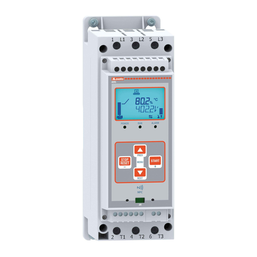
DESCRIPTION – Backlit icon LCD. – 3 status LEDs (power, run, alarm). – Texts for measurements, settings and messages in 6 languages (ENG-ITA-FRA-ESP-POR-DEU). – Front-mounted keypad with 4 keys, for full parameter setting. – AUTOSET wizard for quick configuration in 4 steps of typical applications (pumps, fire fighting pumps, belt conveyors, mixers, fan, general purpose). –... -
Page 3: Autoset Guided Configuration
AUTOSET GUIDED CONFIGURATION – When a factory-new soft starter is first powered up, the AUTOSET configuration wizard launches, to simplify and speed up the configuration and commissioning of the device. – This procedure consists in prompting the user for 4 simple items of information, which enable the ADXL to configure itself with the values most probably suited to the installation in question. –... -
Page 4: Navigating The Display Pages
– In the table below are indicated the parameters which are automatically loaded into the ADXL during the AUTOSET procedure, according to the selected application and duty level. DUTY LEVEL APPLICATION PARAMETER DESCRIPTION LIGHT NORMAL HEAVY P01.02 MAX CURRENT LIMIT 350% 450% 550%... -
Page 5: Operational Status
OPERATIONAL STATUS – During normal operation, if the user does not press the navigation keys to view values, the text bar indicates the starter's status. – The possible statuses are given in the following table, with their explanations: STATUS DISPLAY DESCRIPTION Line absent NO POWER... -
Page 6: Startup Methods
STARTUP METHODS – ADXL supports two main start/stop methods: • Torque ramps (P05.01 = ON) When ADXL is set to work in torque ramp mode, it controls the output voltage with a PID closed-loop control to ensure that the motor delivers a variable torque to the shaft which follows the programmed acceleration and deceleration ramps. -
Page 7: Protections
PROTECTIONS – The ADXL is equipped with a set of integrated protections to safeguard both the starter and the motor. – Some of these are configurable. Their settings are to found in the P04 Protections menu. – The following table summarises the available protections, and their parameters/alarms: PROTECTION MOTOR / STARTER PARAMETERS... -
Page 8: Main Menu
MAIN MENU – To access the main menu, press the L and M buttons together when the motor is stopped. – This provides you access to the following functions: FUNCTION CODE DISPLAY Set password (if enabled – see menu P03 Password ) PASSWORD Launch SETUP menu SETUP... -
Page 9: Limit Thresholds (Limx)
PARAMETER SETTING FROM PC – With the Lovato Electric Xpress remote control and configuration software is possible to read and modify the parameters of the ADXL and save them on a file on the hard disk of the PC, or alternatively you can upload a parameters file from the PC and download it into the soft starter ADXL. -
Page 10: Parameter Setting From Smartphone Or Tablet With Cx02 Wi-Fi Dongle
PARAMETER SETTING FROM SMARTPHONE OR TABLET WITH NFC – You can use the Lovato Electric NFC App, available for Android tablets and smartphones, to program the parameters in a simple, intuitive manner, without the need for cables, and even with the ADXL powered off. -
Page 11: Parameter Table
PARAMETER TABLE P01 – GENERAL Default Range P01.01 Motor nominal current In 30.0 (100%Ie) 15.0…30.0 (50…100%Ie) P01.02 Max (starting) current limit ILt 150…700 P01.03 Initial acceleration step 0…100 P01.04 Acceleration ramp 1…120 P01.05 Deceleration ramp OFF / 1…120 P01.06 End of deceleration threshold 0…100 P01.07 Kick start... - Page 12 P04 – PROTECTIONS Default Range P04.01 Thermal motor protections enable OFF / ON P04.02 Starting thermal protection class P04.03 Run thermal protection class P04.04 Motor thermal protection reset 0…140 P04.05 IN3 input type Digital DIGITAL P04.06 Number of automatic alarm reset attempts OFF / 1…6 P04.07 Automatic alarm reset interval...
- Page 13 P05 - MISCELLANEOUS Default Range P05.01 Torque control P05.02 Torque linearization coefficient 50…150% P05.03 Maximum torque limit OFF / 10…200%Tn P05.04 Delay to start 0.0…20.0 P05.05 Main RS485 function SLAVE SLAVE REM EXP P05.01 – Determines whether the acceleration and deceleration ramps have to be run under torque control or voltage control. P05.02 –...
- Page 14 P09 - MULTIPLE MOTORS (MOTn=1..3) Default Range P09.n.01 Motor nominal current In 30.0 15.0…34.5 (100%Ie) (50…105-115%Ie) P09.n.02 Max (starting) current limit ILt 150…700 P09.n.03 Step at start 0…100 P09.n.04 Acceleration ramp 1…120 P09.n.05 Deceleration ramp OFF / 1…120 P09.n.06 Deceleration end step 0…100 P09.n.07 Kick start OFF / 50…100...
-
Page 15: Alarms
ALARMS – When an alarm occurs, an alarm icon will appear on the display together with an ID code and the description of the alarm in the selected language. – If the page navigation buttons are pressed, the window with the alarm indications momentarily disappears and then reappears after few seconds. –... -
Page 16: Description Of The Alarms
No fans detected. COOLING FAN LOCKED Fan current too high, rotor probably jammed. SYSTEM ERROR Internal error. Please contact Lovato Electric customer service. UA1..4 USER ALARM The user alarm was generated by the activation of the variable associated with menu P13. -
Page 17: Programmable Output Functions Table
PROGRAMMABLE OUTPUT FUNCTIONS TABLE – The following table shows all the functions which can be associated to the programmable digital outputs OUTn. – Each output may be configured with normal or reversed function (NOR or REV). – Some functions require a further numeric parameter defined by index (x) specified by parameter P07.n.02. –... -
Page 18: Connection Diagrams
CONNECTION DIAGRAMS Switch disconnector + ultra-rapid fuses „ MCCB Terminal Parameter Setting Terminal Parameter Setting P06.01.01 START P06.01.01 START P06.02.01 STOP P06.02.01 STOP OUT1 P07.01.01 GLB. ALA. OUT1 P07.01.01 GLB. ALA. OUT2 P07.02.01 LIN. CONT. OUT2 P07.02.01 LIN. CONT. ❷ ❷... -
Page 19: Mechanical Dimensions
MECHANICAL DIMENSIONS ADXL 0030 600 – ADXL 0045 600 – ADXL 0060 600 ADXL 0075 600 – ADXL 0085 600 – ADXL 0115 600 ADXL 0135 600 - ADXL 0162 600... - Page 20 ADXL 0195 600 – ADXL 0250 600 – ADXL 0320 600...
-
Page 21: Terminal Layout
TERMINAL LAYOUT A1 A2 11 14 12 21 24 34 C IN1 IN2 IN3 NOTE. The terminals “FAN +/-”, for the connection of the optional fan (code EXP8004), are present only on soft starters ADXL 0030 600…ADXL 0115 600. Soft starters ADXL 0135 600…ADXL 0320 600 already have two integrated fans as standard. -
Page 22: Choosing The Soft Starter
CHOOSING THE SOFT STARTER Code Starter rated Rated duty power IEC FLA [A] Rated duty power UL current Ie [A] Motor power [kW] Motor power [Hp] Pe@230 Pe@400 Pe@500 Pe@208 Pe@220- Pe@380- Pe@440- Pe@550- 240VAC 415VAC 480VAC 600VAC ADXL 0030 600 18.5 ADXL 0045 600 ADXL 0060 600... -
Page 23: Technical Characteristics
TECHNICAL CHARACTERISTICS Auxiliary supply: terminals A1-A2 Pollution degree environment Degree 2 Us rated voltage 100 - 240V Overvoltage category Operating range 90 - 264V Measurement category Frequency 45 - 66Hz Maximum altitude 1000m without derating (above 1000m, apply a derating of the starter current by 0.5%/100m) Power draw/dissipation Size 1... - Page 24 SOFT STARTER Manuale operativo LOVATO ELECTRIC S.P.A. 24020 GORLE (BERGAMO) ITALIA VIA DON E. MAZZA, 12 TEL. 035 4282111 FAX (Nazionale): 035 4282200 FAX (International): +39 035 4282400 ADXL... E-mail info@ ovato lectric.com www. ovato lectric.com ATTENZIONE! – Leggere attentamente il manuale prima dell’utilizzo e l’installazione.
-
Page 25: Descrizione
DESCRIZIONE – Display LCD a icone, retroilluminato. – 3 LED di stato (alimentazione, rampa/marcia, allarme). – Testi per misure, impostazioni e messaggi in 6 lingue (ENG-ITA-FRA-SPA- POR-DEU). – Tastiera frontale con 4 tasti, permette completa parametrizzazione. – Procedura guidata (wizard) AUTOSET per impostazione rapida in 4 passaggi di applicazioni tipiche (pompa, pompa antincendio, nastro trasportatore, mixer, ventilatore, uso generico). –... -
Page 26: Impostazione Guidata Autoset
IMPOSTAZIONE GUIDATA AUTOSET – Alla prima alimentazione del soft starter nuovo di fabbrica, viene proposta una procedura di impostazione guidata (wizard) denominata AUTOSET, che ha lo scopo di semplificare e velocizzare la configurazione e la messa in servizio dell’avviatore. – Questa procedura consiste nel richiedere all’utente 4 semplici informazioni che consentiranno al soft starter ADXL di auto-programmarsi con dei parametri pre-configurati con valori tipici per la tipologia di installazione in corso. -
Page 27: Navigazione Fra Le Pagine Display
– Nella tabella sottostante sono riportati i parametri caricati automaticamente dalla procedura di AUTOSET nel soft starter ADXL a seconda della tipologia di applicazione e del livello di gravosità selezionati. LIVELLO DI GRAVOSITA’ TIPO DI APPLICAZIONE PARAMETRO DESCRIZIONE LEGGERO NORMALE PESANTE P01.02 LIMITE CORR. -
Page 28: Stati Di Funzionamento
STATI DI FUNZIONAMENTO – Durante il normale funzionamento, se l’utente non preme tasti di navigazione per consultare le misure, la barra alfanumerica indica lo stato in cui si trova l’avviatore. – I possibili stati ed il loro significato sono riassunti nella seguente tabella: STATO DISPLAY DESCRIZIONE... -
Page 29: Metodi Di Avviamento
METODI DI AVVIAMENTO – ADXL supporta due principali metodi di avviamento - arresto: • Rampe di coppia (P05.01 = ON) Quando ADXL è impostato per lavorare a rampa di coppia, regola la tensione in uscita con un controllo ad anello chiuso PID per far erogare al motore una coppia torcente sull’albero variabile nel tempo in modo da seguire le rampe di accelerazione e decelerazione programmate. -
Page 30: Protezioni
PROTEZIONI – ADXL integra una serie di protezioni, dedicate sia alla salvaguardia del motore che dell’avviatore stesso. – Alcune di esse sono parametrizzabili. Le loro impostazioni sono state raccolte nel menu P04 PROTEZIONI. – La seguente tabella riassume le protezioni disponibili e i parametri/allarmi ad esse correlati: PROTEZIONE MOT/AVV PARAMETRI... -
Page 31: Menu Principale
MENU PRINCIPALE – Per accedere al menu principale premere contemporaneamente i tasti L e M quando il motore è fermo. – Esso consente di accedere alle seguenti funzioni: FUNZIONE SIGLA DISPLAY Impostazione della password (se abilitata – vedere menu P03 ) PASSWORD Accesso al menu di impostazione SETUP SETUP... -
Page 32: Soglie Limite (Limx)
IMPOSTAZIONE PARAMETRI DA PC – Con il software di configurazione e controllo remoto Lovato Electric Xpress è possibile leggere e modificare i parametri del soft starter ADXL e salvarli su un file sul disco del PC, oppure scaricare i parametri salvati su un file su PC all’interno del soft starter ADXL. -
Page 33: Impostazione Parametri Da Smartphone O Tablet Con Wifi
IMPOSTAZIONE PARAMETRI DA SMARTPHONE O TABLET CON NFC – Mediante l’APP Lovato Electric NFC Configurator, disponibile per smart devices Android (smartphone e tablet), è possibile accedere alla programmazione dei parametri in un modo semplice ed innovativo, che non ha bisogno di alcun cavo di connessione ed è in grado di operare addirittura con ADXL disalimentato. -
Page 34: Tabella Dei Parametri
TABELLA DEI PARAMETRI P01 – GENERALE Default Range P01.01 Corrente nominale motore In 30.0 (100%Ie) 15.0…30.0 (50…100%Ie) P01.02 Limite corrente di avviamento ILt 150…700 P01.03 Gradino iniziale di accelerazione 10…90 P01.04 Rampa di accelerazione 1…120 P01.05 Rampa di decelerazione OFF / 1…120 P01.06 Gradino di fine decelerazione 0…100... - Page 35 P04 – PROTEZIONI Default Range P04.01 Abilitazione protezione termica motore OFF / ON P04.02 Classe protezione termica all’avviamento P04.03 Classe protezione termica in marcia P04.04 Ripristino protezione termica motore 0…140 P04.05 Tipo ingresso IN3 DIGITALE DIGITALE P04.06 Numero di tentativi reset automatico allarmi OFF / 1…6 P04.07 Intervallo reset automatico allarmi...
- Page 36 P05 – VARIE Default Range P05.01 Controllo di coppia P05.02 Coefficiente di linearizzazione coppia 50…150% P05.03 Limitazione coppia massima OFF / 10…200%Tn P05.04 Ritardo avviamento 0.0…20.0 P05.05 Funzione RS-485 principale SLAVE SLAVE REM EXP P05.01 – Definisce se le rampe di accelerazione e decelerazione devono funzionare a controllo di coppia oppure a controllo di tensione. P05.02 –...
- Page 37 P09 - MOTORI MULTIPLI (MOTn=1..3) Default Range P09.n.01 Corrente nominale motore In 30.0 15.0…30 (100%Ie) (50…100%Ie) P09.n.02 Limite corrente di avviamento ILt 150…700 P09.n.03 Gradino iniziale di accelerazione 10…90 P09.n.04 Rampa di accelerazione 1…120 P09.n.05 Rampa di decelerazione OFF / 1…120 P09.n.06 Gradino di fine decelerazione 0…100 P09.n.07 Kick start all’avviamento...
-
Page 38: Allarmi
ALLARMI – Al sorgere di un allarme, il display mostra una icona di allarme, un codice identificativo e la descrizione dell’allarme nella lingua selezionata. – Se vengono premuti dei tasti di navigazione delle pagine, la finestra con le indicazioni di allarme scompare momentaneamente per poi ricomparire dopo alcuni secondi. –... -
Page 39: Descrizione Degli Allarmi
VENTOLE BLOCCATE Corrente ventole troppo alta, probabile blocco rotazione. ERRORE DI SISTEMA Errore interno al soft starter. Contattare il customer service Lovato Electric. UA1..4 ALLARME UTENTE L’allarme utente è stato generato dall’attivazione della variabile o dell’ingresso associato tramite il menu P13. -
Page 40: Tabella Funzioni Uscite Programmabili
TABELLA FUNZIONI USCITE PROGRAMMABILI – La tabella seguente riporta tutte le funzioni che possono essere associate alle uscite digitali programmabili OUTn. – Ciascuna uscita può essere impostata in modo da avere funzione normale o invertita (NOR o REV). – Alcune funzioni necessitano di un ulteriore parametro numerico, definito con l’indice (x) specificato dal parametro P07.n.02. –... -
Page 41: Schemi Di Connessione
SCHEMI DI CONNESSIONE Sezionatore + fusibili extrarapidi „ MCCB Terminale Parametro Impostazione Terminale Parametro Impostazione P06.01.01 START P06.01.01 START P06.02.01 STOP P06.02.01 STOP OUT1 P07.01.01 ALL. GLB OUT1 P07.01.01 ALL. GLB OUT2 P07.02.01 CONT. LIN OUT2 P07.02.01 CONT. LIN ❷ ❷... -
Page 42: Dimensioni Meccaniche
DIMENSIONI MECCANICHE ADXL 0030 600 – ADXL 0045 600 – ADXL 0060 600 ADXL 0075 600 – ADXL 0085 600 – ADXL 0115 600 ADXL 0135 600 - ADXL 0162 600... - Page 43 ADXL 0195 600 – ADXL 0250 600 – ADXL 0320 600...
-
Page 44: Disposizione Morsetti
DISPOSIZIONE MORSETTI A1 A2 11 14 12 21 24 34 C IN1 IN2 IN3 NOTA. I morsetti “FAN +/-”, per la connessione della ventola opzionale cod. EXP80 04, sono presenti solamente su soft starters ADXL 0030 600…ADXL 0115 600. I soft starters ADXL 0135 600…ADXL 0320 600 hanno due ventole integrate di serie. -
Page 45: Scelta Dell'avviatore
SCELTA DELL’AVVIATORE COD. Corrente nominale di Potenze d’impiego nominali IEC FLA [A] Potenze d’impiego nominali UL impiego Ie [A] Potenza del motore [kW] Potenza del motore [Hp] Pe@230 Pe@400 Pe@500 Pe@208 Pe@220- Pe@380- Pe@440- Pe@550- 240VAC 415VAC 480VAC 600VAC ADXL 0030 600 18.5 ADXL 0045 600 ADXL 0060 600... -
Page 46: Caratteristiche Tecniche
CARATTERISTICHE TECNICHE Alimentazione ausiliaria: morsetti A1-A2 Inquinamento ambiente Grado 2 Tensione nominale Us 100 - 240V Categoria di sovratensione Limiti di funzionamento 90 - 264V Categoria di misura Frequenza 45 - 66Hz Altitudine massima 1000m senza declassamento (sopra i 1000m declassare la corrente dell’avviatore del 0,5%/100m) Potenza assorbita/dissipata Taglia 1...
Need help?
Do you have a question about the ADXL... and is the answer not in the manual?
Questions and answers