Table of Contents
Advertisement
Quick Links
COMMUTATORE AUTOMATICO
DI RETE
ATL10
● Prima di qualsiasi intervento sullo strumento, togliere tensione
dagli ingressi di misura e di alimentazione e cortocircuitare i
trasformatori di corrente.
●Il costruttore non si assume responsabilità in merito alla sicurezza
elettrica in caso di utilizzo improprio del dispositivo.
● I prodotti descritti in questo documento sono suscettibili in
qualsiasi momento di evoluzioni o di modifiche. Le descrizioni ed i
dati a catalogo non possono pertanto avere alcun valore
contrattuale.
● Un interruttore o disgiuntore va compreso nell'impianto elettrico
dell'edificio. Esso deve trovarsi in stretta vicinanza dell'apparecchio
ed essere facilmente raggiungibile da parte dell'operatore. Deve
essere marchiato come il dispositivo di interruzione
dell'apparecchio: IEC/ EN 61010-1 § 6.12.2.1.
● Pulire lo strumento con panno morbido, non usare prodotti
abrasivi, detergenti liquidi o solventi.
INDICE
INSTALLAZIONE ............... ............... ............... .............. 2
SELEZIONE MISURE .......... ............... ............... .............. 3
SELEZIONE MODALITA' OPERATIVA ............... .............. 4
MODALITA' OFF-RESET ..... ............... ............... .............. 4
MODALITA' MAN ............... ............... ............... .............. 4
MODALITA' AUT ............... ............... ............... .............. 4
SIMULAZIONE MANCANZA LINEA PRIORITARIA ........... 5
APPLICAZIONE RETE-GENERATORE .............. .............. 5
APPLICAZIONE RETE-RETE.............. ............... .............. 5
COMANDO DISPOSITIVI DI COMMUTAZIONE . .............. 6
COMANDO INTERRUTTORI MOTORIZZATI ..... .............. 6
COMANDO COMMUTATORI MOTORIZZATI..... .............. 6
COMANDO CONTATTORI .. ............... ............... .............. 6
CONTROLLI DI TENSIONE . ............... ............... .............. 7
ALLARMI ............................ ............... ............... .............. 8
IMPOSTAZIONE DEI PARAMETRI (SETUP)...... .............. 9
TABELLA DEI MENU ........... ............... ............... .............. 9
MENU P1 - DATI NOMINALI............... ............... .............. 9
MENU P2 - DATI GENERALI .............. ............... .............. 10
MENU P3 - CONTROLLO TENSIONE LINEA 1 . .............. 12
MENU P4 - CONTROLLO TENSIONE LINEA 2 . .............. 13
MENU P5 - INGRESSI PROGRAMMABILI......... .............. 14
MENU P6 - USCITE PROGRAMMABILI............. .............. 15
MENU P7 - COMUNICAZIONE SERIALE........... .............. 16
MENU A - ALLARMI .......... ............... ............... .............. 17
MESSAGGI DIAGNOSTICI .. ............... ............... .............. 18
BLOCCO TASTIERA............ ............... ............... .............. 18
CONTROLLO REMOTO ...... ............... ............... .............. 18
MENU COMANDI ............... ............ ............... .............. 18
CONNESSIONI SUL RETRO............... ............... .............. 19
DIMENSIONI MECCANICHE E FORATURA ...... .............. 19
SCHEMI DI COLLEGAMENTO............ ............... .............. 20
CARATTERISTICHE TECNICHE ........ ............... .............. 22
Doc: MHIT101A0309.doc
ATTENZIONE!!
●Leggere attentamente il manuale prima dell'utilizzo
e l'installazione.
● Questi apparecchi devono essere installati da
personale qualificato, nel rispetto delle vigenti
normative impiantistiche, allo scopo di evitare danni
a persone o cose.
............... ............... ............... .............. 2
............... ............... ............... .............. 2
............... ............... ............... .............. 3
............... ............... ............... .............. 3
............... ............... ............... .............. 5
21/01/2010
AUTOMATIC TRANSFER
SWITCH CONTROLLER
ATL10
WARNING!
●Carefully read the manual before the
installation or use.
●This equipment is to be installed by qualified
personnel, complying to current standards, to
avoid damages or safety hazards
●
Before any maintenance operation on the device, remove all the
voltages from measuring and supply inputs and short-circuit the CT
input terminals.
●
Products illustrated herein are subject to alteration and changes
without prior notice.
●Technical data and descriptions in the documentation are
accurate, to the best of our knowledge, but no liabilities for errors,
omissions or contingencies arising there from are accepted.
●A circuit breaker must be included in the electrical installation of
the building. It must be installed close by the equipment and within
easy reach of the operator. It must be marked as the disconnecting
device of the equipment: IEC /EN 61010-1 § 6.12.2.1.
●Clean the instrument with a soft dry cloth; do not use abrasives,
liquid
INDICE
.............. ............... ............... ...............2
.............. ............... ............... ...............2
.............. ............... ............... ...............2
.............. ............... ............... ...............3
MEASURE SELECTION ..... ............... ............... ...............3
.............. ............... ............... ...............3
OPERATING MODE SELECTION....... ............... ...............4
OFF-RESET MODE ............. ............... ............... ...............4
.............. ............... ............... ...............4
.............. ............... ............... ...............4
MAIN LINE FAILURE SIMULATION .... ............... ...............5
UTILITY-TO-GENERATOR APPLICATION......... ...............5
UTILITY-TO-UTILITY APPLICATION .. ............... ...............5
.............. ............... ............... ...............5
CONTROL OF CHANGEOVER DEVICES .......... ...............6
CONTROL OF MOTORISED CIRCUIT BREAKERS ..........6
CONTROL OF CONTACTORS .......... ............... ...............6
VOLTAGE CONTROLS ....... ............... ............... ...............7
ALARMS.............. .............. ............... ............... ...............8
PARAMETERS SETUP........ ............... ............... ...............9
.............. ............... ............... ...............9
MENU P1 - RATINGS ......... ............... ............... ...............9
MENU P2 - GENERAL DATA ............. ............... ...............10
MENU P3 - LINE 1 VOLTAGE CONTROL ......... ...............12
MENU P4 - LINE 2 VOLTAGE CONTROL ......... ...............13
MENU P5 - PROGRAMMABLE INPUTS ............ ...............14
MENU P6 - PROGRAMMABLE OUTPUTS ........ ...............15
MENU P7 - SERIAL COMMUNICATION ............ ...............16
MENU A - ALARMS........... ............... ............... ...............17
DIAGNOSTIC MESSAGES.. ............... ............... ...............18
.............. ............... ............... ...............18
REMOTE CONTROL ........... ............... ............... ...............18
COMMAND MENU............... ............... ............... ...............18
REAR TERMINAL CONNECTIONS .... ............... ...............19
WIRING DIAGRAMS............ ............... ............... ...............20
TECHNICAL CHARACTERISTICS...... ............... ...............22
.
p. 1 / 22
Advertisement
Table of Contents

Related Manuals for LOVATO ELECTRIC ATL10


Summary of Contents for LOVATO ELECTRIC ATL10
-
Page 1: Table Of Contents
COMMUTATORE AUTOMATICO AUTOMATIC TRANSFER DI RETE SWITCH CONTROLLER ATL10 ATL10 ATTENZIONE!! WARNING! ●Leggere attentamente il manuale prima dell’utilizzo ●Carefully read the manual before the e l’installazione. installation or use. ● Questi apparecchi devono essere installati da ●This equipment is to be installed by qualified... -
Page 2: Descrizione
DESCRIZIONE DESCRIPTION • Commutatore automatico di rete a microprocessore. • Microprocessor-based automatic transfer switch controller • Due ingressi di misura tensione trifasi+neutro • Two voltage measuring inputs for three-phase + neutral • Alimentazione DC 12-24-48 V • 12-24-48 VDC power supply •... -
Page 3: Frontale
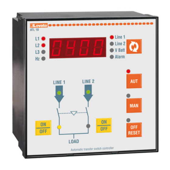
FRONTALE FRONT PANEL • Il frontale dell’apparecchio è provvisto di un display a • The unit front panel is equipped with a LED display LED per indicare le tensioni delle due sorgenti di which shows the voltages of the two supply lines (Line 1 alimentazione (Line 1 e Line 2) e di un relativo tasto and Line 2) with the relevant key for measure selection per scorrere le misure (A) -
Page 4: Selezione Modalita' Operativa
SELEZIONE MODALITA’ OPERATIVA OPERATING MODE SELECTION • Per mezzo dei tre tasti OFF-RESET / MAN / AUT è • The three keys OFF-RESET / MAN / AUT allow to possibile selezionare la modalità operativa desiderata, select the required operating mode, which will be che verrà... -
Page 5: Simulazione Mancanza Linea Prioritaria
P2.14 to allow it to cool down modo da consentirne il raffreddamento • The ATL10 switch sends a start/stop command to the • La centralina ATL10 invia al generatore un comando generator through a relay output and can receive di start/stop attraverso una uscita a relè... -
Page 6: Comando Dispositivi Di Commutazione
COMANDO DISPOSITIVI DI COMMUTAZIONE CONTROL OF CHANGEOVER DEVICES • Per la commutazione delle linee, ATL10 è in grado di • For the line changeover, ATL10 can control different controllare diversi tipi di dispositivi quali interruttori types of devices such as motorised circuit breakers,... -
Page 7: Controlli Di Tensione
CONTROLLI DI TENSIONE VOLTAGE CONTROLS • Tutte le condizioni che servono a stabilire se una • All the conditions which can help establish whether a sorgente di alimentazione è idonea o meno vengono power source is or is not suitable are defined by the definite dall’utente attraverso il menu P1 (dati user through menu P1 (ratings) and menus P3 and P4 nominali) e i menu P3 e P4 (rispettivamente limiti di... -
Page 8: Allarmi
ALLARMI ALARMS • Quando si verifica una situazione di allarme l’ATL10 • When an alarm situation occurs, ATL10 either shows a visualizza un codice sui display code on the displays or lights up a dedicated LED • • For non-retentive alarms, the indication disappears Per gli allarmi non ritenitivi, l’indicazione scompare... -
Page 9: Impostazione Dei Parametri (Setup)
IMPOSTAZIONE DEI PARAMETRI (SETUP) PARAMETERS SETUP • Per accedere al menu impostazioni, con l’apparecchio • To access parameter setup, starting with the unit in OFF- in modalità OFF-RESET, premere i tasti A e D RESET mode, press the A and D keys together for five contemporaneamente per 5 secondi consecutivi, consecutive seconds. -
Page 10: Menu P2 - Dati Generali
MENU P2 – DATI GENERALI MENU P2 –GENERAL DATA Funzione Range Default Function Range Default P2.01 Tipo di U-G = Utility to P2.01 Type of application U-G = Utility to applicazione Generator Generator U-U = Utility to U-U = Utility to Utility Utility P2.02 Controllo OFF –... - Page 11 è stato scollegato dal outputs when working in continuous command mode and carico. ATL10 is in RESET/OFF mode. This parameter can be useful P2.18– Abilita o disabilita il controllo di tensione in when working with contactors.
-
Page 12: Menu P3 - Controllo Tensione Linea 1
MENU P3 – CONTROLLO TENSIONE LINEA 1 MENU P3 – LINE 1 VOLTAGE CONTROL Funzione Range Default Function Range Default P3.01 Soglia tensione 70…98 % P3.01 Minimum voltage 70…98 % minima – sgancio threshold – trip P3.02 Soglia tensione 75…100 % P3.02 Minimum voltage 75…100 % minima –... -
Page 13: Menu P4 - Controllo Tensione Linea 2
MENU P4 – CONTROLLO TENSIONE LINEA 2 MENU P4 – LINE 2 VOLTAGE CONTROL Funzione Range Default Function Range Default P4.01 Soglia tensione 70…98 % P4.01 Minimum voltage 70…98 % minima – sgancio threshold – trip P4.02 Soglia tensione 75…100 % P4.02 Minimum voltage 75…100 % minima –... -
Page 14: Menu P5 - Ingressi Programmabili
1. Se questo open/closed status of line 1 circuit breaker. If this segnale non viene collegato, ATL10 considera lo signal is not connected, ATL10 considers the status stato dell’interruttore corrispondente allo stato delle of the circuit breaker corresponding to the status of... -
Page 15: Menu P6 - Uscite Programmabili
Used in Utilty-Generator l’arresto del gruppo elettrogeno. Utilizzato in applications applicazioni Rete-Generatore ATL10 pronto (Ready) ATL10 Ready Segnala che l’unità è in modo automatico e senza It signals that the unit is in automatic mode and without alarms, ready for intervention... -
Page 16: Menu P7 - Comunicazione Seriale
(continua funzioni uscite programmabili) (continues programmable outputs function) L1.S Stato linea 1 (Line 1 status) L1.S Line 1 Status Uscita eccitata quando esistono tutte le condizioni The output is energized when there are all the per poter collegare il carico alla linea 1 conditions to connect load to line 1 L2.S Stato linea 2 (Line 2 status) -
Page 17: Menu A - Allarmi
MENU A – ALLARMI MENU A – ALARMS Funzione Range Default Funzione Range Default A01.1 Abilitazione A01 OFF / On A01.1 Enable A01 OFF / On A01.2 Ritenitivo OFF / On A01.2 Latch (retenitive) OFF / On A01.3 Blocco interruttore 1 OFF / On A01.3 Lock breaker 1 OFF / On... -
Page 18: Messaggi Diagnostici
TASTIERA SBLOCCATA. REMOTE CONTROL CONTROLLO REMOTO • It is possible to connect ATL10 to a PC through its serial • Tramite la interfaccia seriale è possibile collegare interface to access parameter programming and monitor ATL10 ad un PC per effettuare la programmazione e... -
Page 19: Connessioni Sul Retro
Comando interruttori motorizzati - Motorised circuit breakers control Comando interruttori motorizzati – Control of motorised circuit breakers LINE 1 LINE 2 6.1 L1 RS232 LINE 1 6.3 L3 6.4 N ATL10 7.1 L1 7.2 L2 LINE 2 LINE 1 LINE 2 DIGITAL INPUTS SUPPLY LINE 1... -
Page 20: Schemi Di Collegamento
Comando Commutatore motorizzato – Control of motorised changeover switch LINE 1 LINE 2 6.1 L1 RS232 LINE 1 6.3 L3 6.4 N ATL10 7.1 L1 7.2 L2 LINE 2 LINE 1 LINE 2 DIGITAL INPUTS SUPPLY LINE 1 LINE 2... - Page 21 L1.S, L1.S. • • Impostare l’uscita S.GE in modo che quando l’ATL10 non è alimentato, il Set output S.GE so that when ATL10 is not powered, gen-set must start. generatore si avvii. Doc: MHIT101A0309.doc 21/01/2010 p. 21 / 22...
-
Page 22: Caratteristiche Tecniche
CARATTERISTICHE TECNICHE TECHNICAL CHARACTERISTICS Alimentazione ausiliaria Auxiliary Supply Tensione nominale batteria 12 o 24 o 48V= Nominal battery voltage 12 or 24 or 48V= Massima corrente assorbita 250mA @ 12V=, 130mA @ 24V= e 70mA @ Maximum input current 250mA @ 12V=, 130mA @ 24V= e 70mA @ 48V= 48V= Massima potenza assorbita...
Need help?
Do you have a question about the ATL10 and is the answer not in the manual?
Questions and answers