LOVATO ELECTRIC ATL600 Instruction Manual
Automatic transfer switch controller
Hide thumbs
Also See for ATL600:
- Instruction manual (48 pages) ,
- Installation manual (14 pages) ,
- Installation manual (14 pages)
Table of Contents
Advertisement
ADVERTENCIA
Leer atentamente el manual antes de instalar y utilizar el dispositivo.
Este dispositivo debe ser instalado por personal cualificado conforme a
la normativa de instalación vigente a fin de evitar daños personales o
materiales.
● Antes de realizar cualquier operación en el dispositivo, desconectar la corriente de las
entradas de alimentación y medida.
● El fabricante no se responsabilizará de la seguridad eléctrica en caso de que el dispositivo no
se utilice de forma adecuada.
● Los productos descritos en este documento se pueden actualizar o modificar en cualquier
momento. Por consiguiente, las descripciones y los datos técnicos aquí contenidos no tienen
valor contractual.
● La instalación eléctrica del edificio debe disponer de un interruptor o disyuntor. Este debe
encontrarse cerca del dispositivo, en un lugar al que el usuario pueda acceder con facilidad.
Además, debe estar identificado como tal (IEC/ EN 61010-1 § 6.12.2.1).
● Limpiar el dispositivo con un trapo suave; no utilizar productos abrasivos, detergentes líquidos
o disolventes.
Índice
Smartphone
frontal
Doc: I414EGB03_16.doc
ATL600 - ATL610
CONMUTADOR AUTOMÁTICO DE RED
MANUAL DE INSTRUCCIONES
Página
2
2
3
3
3
4
4
5
5
7
8
8
8
9
9
9
10
10
11
11
11
11
12
13
20
20
21
21
22
22
23
24
26
31
31
31
33
E
ATL600 - ATL610
AUTOMATIC TRANSFER SWITCH CONTROLLER
INSTRUCTIONS MANUAL
WARNING!
Carefully read the manual before the installation or use.
This equipment is to be installed by qualified personnel, complying to
current standards, to avoid damages or safety hazards.
● Before any maintenance operation on the device, remove all the voltages from measuring and
supply inputs.
● Products illustrated herein are subject to alteration and changes without prior notice.
● Technical data and descriptions in the documentation are accurate, to the best of our
knowledge, but no liabilities for errors, omissions or contingencies arising there from are
accepted.
● A circuit breaker must be included in the electrical installation of the building. It must be
installed close by the equipment and within easy reach of the operator.
It must be marked as the disconnecting device of the equipment:
IEC /EN 61010-1 § 6.12.2.1.
● Clean the instrument with a soft dry cloth; do not use abrasives, liquid detergents or solvents
Index
02/12/2014
.
Page
2
2
3
3
3
4
4
5
5
7
8
8
8
9
9
9
10
10
11
11
11
11
12
13
20
20
21
21
22
22
23
24
26
31
31
31
33
p. 1 / 33
Advertisement
Table of Contents

Related Manuals for LOVATO ELECTRIC ATL600


Summary of Contents for LOVATO ELECTRIC ATL600
-
Page 1: Table Of Contents
ATL600 - ATL610 ATL600 - ATL610 CONMUTADOR AUTOMÁTICO DE RED AUTOMATIC TRANSFER SWITCH CONTROLLER MANUAL DE INSTRUCCIONES INSTRUCTIONS MANUAL ADVERTENCIA WARNING! Leer atentamente el manual antes de instalar y utilizar el dispositivo. Carefully read the manual before the installation or use. -
Page 2: Introducción
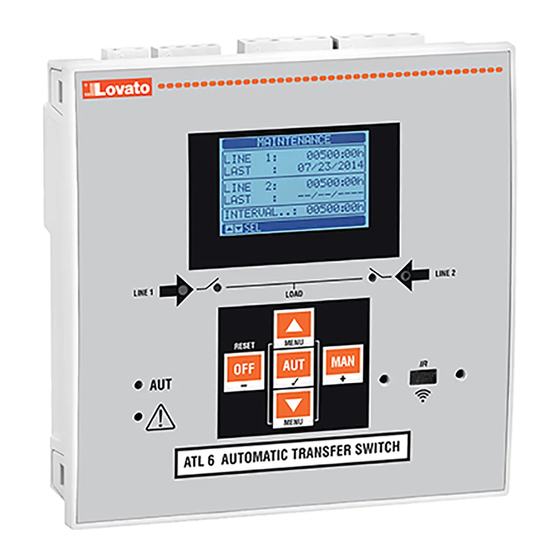
Introducción Introduction El diseño de las unidades de control ATL600 y ATL610 incorpora las The ATL600 and ATL610 control units have been designed to offer state- funciones más avanzadas para aplicaciones de supervisión y conmutación of-the-art functions for automatic transfer switching applications between automática entre dos líneas de alimentación trifásica. -
Page 3: Funciones De Las Teclas Frontales
1 está abierto o cerrado. El parpadeo mismatchbetweenthe desired state of the breaker andits true state indica que el estado previsto del ATL600 y el estado real detectado por la detected by the feedback input. -
Page 4: Puesta En Tensión
Puesta en tensión Power-up ATL600 tiene una alimentación de 100-240 V CA. ATL600 has 100-240VAC supply. ATL610 utiliza 100-240 V CA o 12-24 V CC. Cuando existen al mismo ATL610 has 100-240VAC or 12-24VDC supply. In the case of the tiempo ambas opciones, se concede prioridad a la corriente alterna. -
Page 5: Acceso Con Contraseña
Acceso con contraseña Password access La contraseña sirve para permitir o bloquear el acceso al menú de The password is used to enable or lock the access to setting menu configuración y al menú de comandos. (setup) and to commands menu. ... - Page 6 Estadísticas Statistics Line 2 AUT mode Contador de MAN mode Line1 Línea 1 Línea 2 Contador de commutation conmutación commutation conmutación counter en modo AUT counter en modo Contador de Time lapse Alarm counter Tiempo alarmas A03 with load transcurrido A03 A04 supplied con suministro...
-
Page 7: Capacidad De Expansión
Lista de eventos Event List Event code Código de evento Fecha y hora de Descripción evento Description de evento of event Nota: algunas de las páginas mencionadas arriba podrían no mostrarse si Note: Some of the pages listed above may not be displayed if the la función correspondiente no está... -
Page 8: Recursos Adicionales
En la siguiente tabla aparecen todas las variables internas que gestiona The following table groups all the I/O and the internal variables managed la unidad ATL600 y su rango correspondiente (número de variables por by the ATL600, with highlighting of their range (variables number per tipo). -
Page 9: Umbrales Límite (Limx)
Variables de control remoto (REMx) Remote-controlled variables (REMx) Las unidades ATL600 y ATL610 ofrecen la posibilidad de gestionar un ATL600 and ATL610 can manage up to 8 remote-controlled variables máximo de 8 variables por control remoto (REM1 a REM8). -
Page 10: Prueba Automática
La alarma puede generarse por varios motivos, como cuando se supera The condition that generates the alarm can be, for instance, the un umbral. En este caso, el origen será uno de los umbrales límite LIMx. overcoming of a threshold. In this case, the source will be one of the limit ... -
Page 11: Bloqueo Del Teclado
Bloqueo del teclado Keypad lock • El teclado de la unidad ATL6.. puede bloquearse mediante lo • The ATL keypad can be locked either by: siguiente: programmable input. una entrada programable a particular procedure from front keys. un procedimiento especial que se realiza con las teclas frontales ATLSW(ATL Remote control). -
Page 12: Configuración De Parámetros (Setup) Mediante El Panel
SAM1 – smartphone SAM1 – tablet Configuración de parámetros mediante el panel frontal Parameter setting (setup) from front panel Para acceder al menú de programación de parámetros: To open the parameters programming menu (setup): Poner la placa en modo OFF Turn the unit in OFF mode En la pantalla de medidas normal, pulsar ▲... -
Page 13: Tabla De Parámetros
Se muestra el código, la descripción y el valor actual de todos los Each parameter is shown with code, description and actual setting parámetros. value. Código parámetro Valor actual Parameter code Present setting value Descripción Parámetro Parameter Selected parameter parámetro seleccionado description... - Page 14 P01.04: regulación del contraste de la pantalla LCD. P01.05 – Display backlight high adjustment. P01.05: regulación de la retroiluminación de la pantalla en un valor de alta intensidad. P01.07 – Display backlight low delay. P01.05: regulación de la retroiluminación de la pantalla en un valor de baja intensidad. P01.08 –...
- Page 15 P05.13 Modo de funcionamiento EJP Normal Normal P05.12 Inhibition automatic return on priority LINE OFF / ON P05.13 EJP mode Normal Normal EJP-T EJP-T P05.14 Retardo de arranque EJP 0-240 P05.15 Retardo de conmutación EJP 0-240 P05.14 EJP start delay 0-240 P05.16 Bloqueo de reconmutación EJP OFF/ON...
- Page 16 las señales de las entradas EJP lo permiten. source lines. P05.17: cuando está activado, la carga se conmuta a la línea alternativa, además de P05.18 – Duration of the opening pulse on the minimum voltage coils. generarse la alarma de realimentación correspondiente (A03 o A04), cuando falla el P05.19 –...
- Page 17 momento en que se abre el contactor de red. the generator and when the engine actually stops. P06.20: duración máxima del ciclo de refrigeración. Por ejemplo: tiempo que transcurre entre la desconexión de la carga del generador y la parada efectiva del motor. M07 –...
- Page 18 No se utiliza con otros tipos de módulos de comunicación. between the Ethernet and serial ports. P08.n.09: función del canal de comunicación. Esclavo = esclavo modbus; puerta de enlace = P08.n.10 – Enabling TCP-IP connection. Server = Awaits connection from a remote client. vínculo entre el puerto Ethernet y el puerto serie Client = Establishes a connection to the remote server.
- Page 19 P12.03 Salida de modo operativo M – O M – O … P12.01 – Defines the programmed maintenance period, in hours. If set to OFF, this service … interval is disabled. P12.01: define el periodo de mantenimiento programado, expresado en horas. Cuando se P12.02 –...
-
Page 20: Alarmas
P15.n.01 Origen de alarma OUTx INPx LIMx OUTx REMx LIMx P15.n.02 Channel number (x) OFF/1...99 REMx P15.n.03 Text (text – 20 P15.n.02 Número de canal (x) OFF/1 a 99 char) P15.n.03 Texto (texto 20 P15.n.04 Breaker opening caracteres) P15.n.04 Apertura de interruptor Note: this menu is divided into 4 sections for user alarms UA1…UA4. -
Page 21: Tabla De Alarmas
Tabla de alarmas Alarm table CÓD. Descripción DESCRIPTION A01 Battery voltage too low A01 Tensión de la batería demasiado baja ● ● ● ● ● ● ● ● A02 Tensión de la batería demasiado alta ● ● ● ● A02 Battery voltage too high ●... -
Page 22: Tabla De Funciones De Entrada Programables
Se genera cuando el número de maniobras correspondiente a Alarm generated when the number of operations for LINE 1 la LÍNEA 1 alcanza el valor configurado en el menú M12. reach the value sated in the menu M12. Use the Mantenimiento en Maintenance Utilizar el menú... -
Page 23: Tabla De Funciones De Salida
Simulación de tecla MAN El cierre de la entrada equivale a pulsar la tecla. Key OFF simulation Closing the input is the equivalent of pressing the key. Simulación de tecla AUT El cierre de la entrada equivale a pulsar la tecla. Key MAN simulation Closing the input is the equivalent of pressing the key. -
Page 24: Instalación
Instalación Installation La unidad ATL600 está diseñada para montarse empotrada. Cuando ATL600 is designed for flush-mount installation. With proper mounting, it está correctamente montada, la junta opcional garantiza una protección guarantees with the optional gasket IP65 front protection. -
Page 25: Esquemas De Conexión
Esquemas de conexión Wiring diagrams Control de interruptores motorizados Control of motorised circuit breakers Programación de parámetros correspondiente al esquema de la figura Parameter setting for the wiring diagram in picture Terminal Código parámetro Configuración Terminal Parameter code Setting P05.07 Control de interruptores por impulsos o continuo Breaker pulse or breaker continuous 15(INP1) -
Page 26: Wiring Diagrams
Control de conmutación motorizado Control of motorized changeover switch Programación de parámetros correspondiente al esquema de la figura Parameter setting for the wiring diagram in picture Terminal Código parámetro Configuración Terminal Parameter code Setting P05.07 Control de conmutación por impulsos o continuo Changeover pulse or Changeover continuous 15(INP1) P10.01.01... - Page 27 Control de contactores Control of contactors Programación de parámetros correspondiente al esquema de la figura Parameter setting for the wiring diagram in picture Terminal Código parámetro Configuración Terminal Parameter code Setting P05.07 Contactores Contactors 15(INP1) P10.01.01 Interruptor de línea 1 cerrado (realimentación 1) Line 1 breaker closed (Feedback 1) 16(INP2) P10.02.01...
- Page 28 Dual power supply implementation with auxiliary voltage control by dispositivo Lovato Electric con código ATLDPS1 Lovato Electric dual power supply relay code ATLDPS1 Alimenatción dual con control de tensión auxiliar mediante relé de Dual Power Supply implementation with auxiliary voltage control by monitorización de tensión...
- Page 29 Line 2 coming from generator Línea 2 procedente del generador Control de tensión auxiliar mediante ATL600 + Dual Power Supply de CA opcional (sistema sin Auxiliary voltage control by ATL600 + optional AC Dual Power Supply (battery supply not alimentación por batería)
-
Page 30: Disposición De Los Terminales
Disposición de los terminales Terminals position Dimensiones mecánicas y escotadura del panel (mm) Mechanical dimensions and front panel cut-out (mm) Doc: I414EGB03_16.doc 02/12/2014 p. 30 / 33... -
Page 31: Características Técnicas
Características técnicas Technical characteristics Alimentación de CA: terminales 13, 14 AC Supply: terminals 13, 14 100 - 240 V~ 100 - 240V~ Tensión nominal Us Rated voltage Us 110 - 250 V= 110 - 250V= 90 - 264 V~ 90 - 264V~ Límites de funcionamiento Operating voltage range 93,5 - 300 V=... -
Page 32: Manual Revision History
Tensión de aislamiento Insulation voltage Alimentación de CA AC Supply Tensión nominal de aislamiento Ui 250 V~ Rated insulation voltage Ui 250V~ Tensión soportada nominal a impulsos Uimp 7,3 kV Rated impulse withstand voltage Uimp 7.3kV Tensión soportada a frecuencia de 3 kV Power frequency withstand voltage funcionamiento... -
Page 33: Historial De Revisiones Del Manual
29/02/2016 Modificación del parámetro P05.20 29/02/2016 Changed parameters P05.20 Doc: I414EGB03_16.doc 02/12/2014 p. 33 / 33...
Need help?
Do you have a question about the ATL600 and is the answer not in the manual?
Questions and answers