Table of Contents
Advertisement
LOV TO ELECTRIC S.P. .
24020 GORLE (BERGAMO) ITALIA
VIA DON E. MAZZA, 12
TEL. +39 035 4282111
L
E
E-mail info@
ovato
lectric.com
L
E
Web
www.
ovato
lectric.com
W RNING!
- Read the manual carefully before installation and use.
- These devices must be installed by qualified personnel, in compliance with current plant-engineering regulations, in order to avoid damage toi persons or property.
- Before any maintenance operation on the device, switch off power supply from measuring and supply inputs.
- The manufacturer assumes no responsibility for electrical safety in the event of improper use of the device.
- The products described in this document are subject to updates or modifications at any time. Data and descriptions in the catalogue therefore do not have any contractual value.
- The building's electrical system must incorporate a switch or circuit breaker. It must be installed close to the equipment and within easy reach of the operator. It must be marked as the disconnecting device of the
equipment: IEC/EN/BS 61010-1 § 6.11.3.1.
- Clean the instrument with a soft cloth. Do not use abrasives, liquid detergents or solvents.
CONTENTS
1. Description . . . . . . . . . . . . . . . . . . . . . . . . . . . . . . . . . . . . . . . . . . . . . . . . . . . . . . . . . . . . . . . . . . . . . . . . . . . . . . . . . . . . . . . . . . . . . . . . . . . . . . . . . . . . . . . . . . . . . . . . . . . . . . . . . . . . . . . . . . . . . . . . . . . . . . . . .
2. General characteristics . . . . . . . . . . . . . . . . . . . . . . . . . . . . . . . . . . . . . . . . . . . . . . . . . . . . . . . . . . . . . . . . . . . . . . . . . . . . . . . . . . . . . . . . . . . . . . . . . . . . . . . . . . . . . . . . . . . . . . . . . . . . . . . . . . . . . . . . . . . . . . . .
3. Frontal layout . . . . . . . . . . . . . . . . . . . . . . . . . . . . . . . . . . . . . . . . . . . . . . . . . . . . . . . . . . . . . . . . . . . . . . . . . . . . . . . . . . . . . . . . . . . . . . . . . . . . . . . . . . . . . . . . . . . . . . . . . . . . . . . . . . . . . . . . . . . . . . . . . . . . . . . .
4. Status LED . . . . . . . . . . . . . . . . . . . . . . . . . . . . . . . . . . . . . . . . . . . . . . . . . . . . . . . . . . . . . . . . . . . . . . . . . . . . . . . . . . . . . . . . . . . . . . . . . . . . . . . . . . . . . . . . . . . . . . . . . . . . . . . . . . . . . . . . . . . . . . . . . . . . . . . . .
5. Starting and stopping ramps management . . . . . . . . . . . . . . . . . . . . . . . . . . . . . . . . . . . . . . . . . . . . . . . . . . . . . . . . . . . . . . . . . . . . . . . . . . . . . . . . . . . . . . . . . . . . . . . . . . . . . . . . . . . . . . . . . . . . . . . . . . . . . . . . .
5.1 Parameters for the management of the starting and stopping ramps . . . . . . . . . . . . . . . . . . . . . . . . . . . . . . . . . . . . . . . . . . . . . . . . . . . . . . . . . . . . . . . . . . . . . . . . . . . . . . . . . . . . . . . . . . . . . . . . . . . . . . . .
5.2 Management of starting ramps with current limit (only for ADXNP) . . . . . . . . . . . . . . . . . . . . . . . . . . . . . . . . . . . . . . . . . . . . . . . . . . . . . . . . . . . . . . . . . . . . . . . . . . . . . . . . . . . . . . . . . . . . . . . . . . . . . . . . .
6. Functional diagram . . . . . . . . . . . . . . . . . . . . . . . . . . . . . . . . . . . . . . . . . . . . . . . . . . . . . . . . . . . . . . . . . . . . . . . . . . . . . . . . . . . . . . . . . . . . . . . . . . . . . . . . . . . . . . . . . . . . . . . . . . . . . . . . . . . . . . . . . . . . . . . . . . .
7. Protections . . . . . . . . . . . . . . . . . . . . . . . . . . . . . . . . . . . . . . . . . . . . . . . . . . . . . . . . . . . . . . . . . . . . . . . . . . . . . . . . . . . . . . . . . . . . . . . . . . . . . . . . . . . . . . . . . . . . . . . . . . . . . . . . . . . . . . . . . . . . . . . . . . . . . . . . .
7.1 Enabling the phase sequence control (ADXNB) . . . . . . . . . . . . . . . . . . . . . . . . . . . . . . . . . . . . . . . . . . . . . . . . . . . . . . . . . . . . . . . . . . . . . . . . . . . . . . . . . . . . . . . . . . . . . . . . . . . . . . . . . . . . . . . . . . . . . . . . .
7.2 Motor thermal overload protection . . . . . . . . . . . . . . . . . . . . . . . . . . . . . . . . . . . . . . . . . . . . . . . . . . . . . . . . . . . . . . . . . . . . . . . . . . . . . . . . . . . . . . . . . . . . . . . . . . . . . . . . . . . . . . . . . . . . . . . . . . . . . . . . . .
7.3 Soft starter thermal protection . . . . . . . . . . . . . . . . . . . . . . . . . . . . . . . . . . . . . . . . . . . . . . . . . . . . . . . . . . . . . . . . . . . . . . . . . . . . . . . . . . . . . . . . . . . . . . . . . . . . . . . . . . . . . . . . . . . . . . . . . . . . . . . . . . . . .
8. Parameters setup . . . . . . . . . . . . . . . . . . . . . . . . . . . . . . . . . . . . . . . . . . . . . . . . . . . . . . . . . . . . . . . . . . . . . . . . . . . . . . . . . . . . . . . . . . . . . . . . . . . . . . . . . . . . . . . . . . . . . . . . . . . . . . . . . . . . . . . . . . . . . . . . . . . .
8.1 Setting of parameters with potentiometers (ADXNB, ADXNP) . . . . . . . . . . . . . . . . . . . . . . . . . . . . . . . . . . . . . . . . . . . . . . . . . . . . . . . . . . . . . . . . . . . . . . . . . . . . . . . . . . . . . . . . . . . . . . . . . . . . . . . . . . . . .
8.2 Setting of parameters with NFC (ADXNF, ADXNP) . . . . . . . . . . . . . . . . . . . . . . . . . . . . . . . . . . . . . . . . . . . . . . . . . . . . . . . . . . . . . . . . . . . . . . . . . . . . . . . . . . . . . . . . . . . . . . . . . . . . . . . . . . . . . . . . . . . . . . .
8.3 Setting of parameters with IR optical port (ADXNP) . . . . . . . . . . . . . . . . . . . . . . . . . . . . . . . . . . . . . . . . . . . . . . . . . . . . . . . . . . . . . . . . . . . . . . . . . . . . . . . . . . . . . . . . . . . . . . . . . . . . . . . . . . . . . . . . . . . . .
8.4 Suggested settings for typical applications . . . . . . . . . . . . . . . . . . . . . . . . . . . . . . . . . . . . . . . . . . . . . . . . . . . . . . . . . . . . . . . . . . . . . . . . . . . . . . . . . . . . . . . . . . . . . . . . . . . . . . . . . . . . . . . . . . . . . . . . . . . .
9. Parameters table . . . . . . . . . . . . . . . . . . . . . . . . . . . . . . . . . . . . . . . . . . . . . . . . . . . . . . . . . . . . . . . . . . . . . . . . . . . . . . . . . . . . . . . . . . . . . . . . . . . . . . . . . . . . . . . . . . . . . . . . . . . . . . . . . . . . . . . . . . . . . . . . . . . . .
9.1 Parameters menu . . . . . . . . . . . . . . . . . . . . . . . . . . . . . . . . . . . . . . . . . . . . . . . . . . . . . . . . . . . . . . . . . . . . . . . . . . . . . . . . . . . . . . . . . . . . . . . . . . . . . . . . . . . . . . . . . . . . . . . . . . . . . . . . . . . . . . . . . . . . . . . .
9.2 ADXNF parameters table (NFC version) . . . . . . . . . . . . . . . . . . . . . . . . . . . . . . . . . . . . . . . . . . . . . . . . . . . . . . . . . . . . . . . . . . . . . . . . . . . . . . . . . . . . . . . . . . . . . . . . . . . . . . . . . . . . . . . . . . . . . . . . . . . . . . .
9.3 ADXNP parameters table (advanced version) . . . . . . . . . . . . . . . . . . . . . . . . . . . . . . . . . . . . . . . . . . . . . . . . . . . . . . . . . . . . . . . . . . . . . . . . . . . . . . . . . . . . . . . . . . . . . . . . . . . . . . . . . . . . . . . . . . . . . . . . . .
10. Alarms . . . . . . . . . . . . . . . . . . . . . . . . . . . . . . . . . . . . . . . . . . . . . . . . . . . . . . . . . . . . . . . . . . . . . . . . . . . . . . . . . . . . . . . . . . . . . . . . . . . . . . . . . . . . . . . . . . . . . . . . . . . . . . . . . . . . . . . . . . . . . . . . . . . . . . . . . . . .
10.1 Alarms properties table . . . . . . . . . . . . . . . . . . . . . . . . . . . . . . . . . . . . . . . . . . . . . . . . . . . . . . . . . . . . . . . . . . . . . . . . . . . . . . . . . . . . . . . . . . . . . . . . . . . . . . . . . . . . . . . . . . . . . . . . . . . . . . . . . . . . . . . . . . .
10.2 Alarms description . . . . . . . . . . . . . . . . . . . . . . . . . . . . . . . . . . . . . . . . . . . . . . . . . . . . . . . . . . . . . . . . . . . . . . . . . . . . . . . . . . . . . . . . . . . . . . . . . . . . . . . . . . . . . . . . . . . . . . . . . . . . . . . . . . . . . . . . . . . . . . .
11. Programmable outputs function table . . . . . . . . . . . . . . . . . . . . . . . . . . . . . . . . . . . . . . . . . . . . . . . . . . . . . . . . . . . . . . . . . . . . . . . . . . . . . . . . . . . . . . . . . . . . . . . . . . . . . . . . . . . . . . . . . . . . . . . . . . . . . . . . . . . .
11.1 Programmable outputs default settings . . . . . . . . . . . . . . . . . . . . . . . . . . . . . . . . . . . . . . . . . . . . . . . . . . . . . . . . . . . . . . . . . . . . . . . . . . . . . . . . . . . . . . . . . . . . . . . . . . . . . . . . . . . . . . . . . . . . . . . . . . . . . . .
12. Optional RS485 communication (for ADXNP only) . . . . . . . . . . . . . . . . . . . . . . . . . . . . . . . . . . . . . . . . . . . . . . . . . . . . . . . . . . . . . . . . . . . . . . . . . . . . . . . . . . . . . . . . . . . . . . . . . . . . . . . . . . . . . . . . . . . . . . . . . .
12.1 Modbus address table . . . . . . . . . . . . . . . . . . . . . . . . . . . . . . . . . . . . . . . . . . . . . . . . . . . . . . . . . . . . . . . . . . . . . . . . . . . . . . . . . . . . . . . . . . . . . . . . . . . . . . . . . . . . . . . . . . . . . . . . . . . . . . . . . . . . . . . . . . . .
12.1.1 Measures available on the Modbus protocol . . . . . . . . . . . . . . . . . . . . . . . . . . . . . . . . . . . . . . . . . . . . . . . . . . . . . . . . . . . . . . . . . . . . . . . . . . . . . . . . . . . . . . . . . . . . . . . . . . . . . . . . . . . . . . . . . . . . .
12.1.2 Start and Stop commands via Modbus . . . . . . . . . . . . . . . . . . . . . . . . . . . . . . . . . . . . . . . . . . . . . . . . . . . . . . . . . . . . . . . . . . . . . . . . . . . . . . . . . . . . . . . . . . . . . . . . . . . . . . . . . . . . . . . . . . . . . . . . .
12.1.3 Parameters setting via Modbus . . . . . . . . . . . . . . . . . . . . . . . . . . . . . . . . . . . . . . . . . . . . . . . . . . . . . . . . . . . . . . . . . . . . . . . . . . . . . . . . . . . . . . . . . . . . . . . . . . . . . . . . . . . . . . . . . . . . . . . . . . . . . . .
13. Recommendations . . . . . . . . . . . . . . . . . . . . . . . . . . . . . . . . . . . . . . . . . . . . . . . . . . . . . . . . . . . . . . . . . . . . . . . . . . . . . . . . . . . . . . . . . . . . . . . . . . . . . . . . . . . . . . . . . . . . . . . . . . . . . . . . . . . . . . . . . . . . . . . . . . .
14. Wiring diagrams . . . . . . . . . . . . . . . . . . . . . . . . . . . . . . . . . . . . . . . . . . . . . . . . . . . . . . . . . . . . . . . . . . . . . . . . . . . . . . . . . . . . . . . . . . . . . . . . . . . . . . . . . . . . . . . . . . . . . . . . . . . . . . . . . . . . . . . . . . . . . . . . . . . . .
15. Mechanical dimensions . . . . . . . . . . . . . . . . . . . . . . . . . . . . . . . . . . . . . . . . . . . . . . . . . . . . . . . . . . . . . . . . . . . . . . . . . . . . . . . . . . . . . . . . . . . . . . . . . . . . . . . . . . . . . . . . . . . . . . . . . . . . . . . . . . . . . . . . . . . . . . .
16. Terminal layout . . . . . . . . . . . . . . . . . . . . . . . . . . . . . . . . . . . . . . . . . . . . . . . . . . . . . . . . . . . . . . . . . . . . . . . . . . . . . . . . . . . . . . . . . . . . . . . . . . . . . . . . . . . . . . . . . . . . . . . . . . . . . . . . . . . . . . . . . . . . . . . . . . . . . .
. . . . . . . . . . . . . . . . . . . . . . . . . . . . . . . . . . . . . . . . . . . . . . . . . . . . . . . . . . . . . . . . . . . . . . . . . . . . . . . . . . . . . . . . . . . . . . . . . . . . . . . . . . . . . . . . . . . . . . . . . . . . . . . . . . . . . . . . . . . . . . . . . . . . . . . . . . . . . .
18. Number of starts per hour . . . . . . . . . . . . . . . . . . . . . . . . . . . . . . . . . . . . . . . . . . . . . . . . . . . . . . . . . . . . . . . . . . . . . . . . . . . . . . . . . . . . . . . . . . . . . . . . . . . . . . . . . . . . . . . . . . . . . . . . . . . . . . . . . . . . . . . . . . . . .
19. Choosing the soft starter . . . . . . . . . . . . . . . . . . . . . . . . . . . . . . . . . . . . . . . . . . . . . . . . . . . . . . . . . . . . . . . . . . . . . . . . . . . . . . . . . . . . . . . . . . . . . . . . . . . . . . . . . . . . . . . . . . . . . . . . . . . . . . . . . . . . . . . . . . . . . .
20. Coordination tables . . . . . . . . . . . . . . . . . . . . . . . . . . . . . . . . . . . . . . . . . . . . . . . . . . . . . . . . . . . . . . . . . . . . . . . . . . . . . . . . . . . . . . . . . . . . . . . . . . . . . . . . . . . . . . . . . . . . . . . . . . . . . . . . . . . . . . . . . . . . . . . . . . .
20.1 Coordination with line contactor . . . . . . . . . . . . . . . . . . . . . . . . . . . . . . . . . . . . . . . . . . . . . . . . . . . . . . . . . . . . . . . . . . . . . . . . . . . . . . . . . . . . . . . . . . . . . . . . . . . . . . . . . . . . . . . . . . . . . . . . . . . . . . . . . . . .
20.2 Coordination with thermal overload relay (ADXNB... and ADXNF...) . . . . . . . . . . . . . . . . . . . . . . . . . . . . . . . . . . . . . . . . . . . . . . . . . . . . . . . . . . . . . . . . . . . . . . . . . . . . . . . . . . . . . . . . . . . . . . . . . . . . . . . . .
20.3 Type 1 coordination with motor protection circuit breaker . . . . . . . . . . . . . . . . . . . . . . . . . . . . . . . . . . . . . . . . . . . . . . . . . . . . . . . . . . . . . . . . . . . . . . . . . . . . . . . . . . . . . . . . . . . . . . . . . . . . . . . . . . . . . . . .
20.4 Type 2 coordination (IEC/EN/BS 60947-4-2) . . . . . . . . . . . . . . . . . . . . . . . . . . . . . . . . . . . . . . . . . . . . . . . . . . . . . . . . . . . . . . . . . . . . . . . . . . . . . . . . . . . . . . . . . . . . . . . . . . . . . . . . . . . . . . . . . . . . . . . . . . .
20.5 Coordination according to UL60947-4-2 . . . . . . . . . . . . . . . . . . . . . . . . . . . . . . . . . . . . . . . . . . . . . . . . . . . . . . . . . . . . . . . . . . . . . . . . . . . . . . . . . . . . . . . . . . . . . . . . . . . . . . . . . . . . . . . . . . . . . . . . . . . . . .
21. Technical characteristics . . . . . . . . . . . . . . . . . . . . . . . . . . . . . . . . . . . . . . . . . . . . . . . . . . . . . . . . . . . . . . . . . . . . . . . . . . . . . . . . . . . . . . . . . . . . . . . . . . . . . . . . . . . . . . . . . . . . . . . . . . . . . . . . . . . . . . . . . . . . . . .
GB
SOFT ST RTER
Instructions manual
DXN...
G
B
Page
2
2
3
3
4
4
5
5
6
6
6
6
7
7
7
9
9
10
10
10
11
13
13
13
14
14
14
15
15
15
15
16
16
17
17
18
18
18
19
19
19
20
20
20
21
1
Advertisement
Table of Contents

Related Manuals for LOVATO ELECTRIC ADXN Series


Summary of Contents for LOVATO ELECTRIC ADXN Series
-
Page 1: Table Of Contents
SOFT ST RTER Instructions manual LOV TO ELECTRIC S.P. . 24020 GORLE (BERGAMO) ITALIA VIA DON E. MAZZA, 12 TEL. +39 035 4282111 E-mail info@ ovato lectric.com www. ovato lectric.com DXN... W RNING! – Read the manual carefully before installation and use. –... -
Page 2: Description
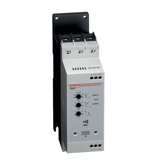
DESCRIPTION The soft starters ADXN series are the ideal solution for those who need a simple, compact and fast to configure product for the gradual control of the starting and stopping of the motors. Their versatility makes them suitable for several applications such as the control of pumps, fans, conveyor belts, compressors and they are available with rated currents from 6 to 45A. -
Page 3: Frontal Layout
FRONTAL LAYOUT Basic version DXNB NFC version DXNF dvanced version DXNP Auxiliary supply voltage Auxiliary supply voltage Auxiliary supply voltage (A1-A2) and start input (A1-A2) and start input (A1-A2) and start input (ST) (ST) (ST) 3 potentiometers 3 potentiometers for basic settings: for basic settings –... -
Page 4: Starting And Stopping Ramps Management
STARTING AND STOPPING RAMPS MANAGEMENT 5.1 PARAMETERS FOR THE MANAGEMENT OF THE STARTING AND STOPPING RAMPS The soft starters ADXN work with voltage ramps, which consist of generate a ramp by supplying voltage from the starting value (which can be set from the 30% to the 80% of the line voltage Ue) up to the 100% of the line voltage in the acceleration time set with progressive growth. -
Page 5: Management Of Starting Ramps With Current Limit (Only For Adxnp)
5.2 MANAGEMENT OF STARTING RAMPS WITH CURRENT LIMIT (ONLY FOR ADXNP) The advanced version ADXNP integrates current transformers, which allow to limit the current during the starting phase below a programmable threshold (P01.07) and to adapt the acceleration ramp according to the load conditions. -
Page 6: Protections
PROTECTIONS All the soft starters ADXN integrate the protection against overtemperature, measured by an integrated temperature sensor. The versions provided with NFC connectivity (ADXNF and ADXNP) provides additional functions dedicated to the protection of the motor and the soft starter itself, some of which are programmable. The following table summarizes the protections available in the different versions and their associated parameters and alarms. -
Page 7: Parameters Setup
PARAMETERS SETUP 8.1 SETTING OF PARAMETERS WITH POTENTIOMETERS (ADXNB, ADXNP) The soft starters type ADXNB (basic version) and ADXNP (advanced version) have on the front three potentiometers for the setting of the basic parameters: Starting voltage 30 - 80%U cceleration ramp time 1 - 20 seconds Deceleration ramp time 0 - 20 seconds (0 = ramp disabled, free wheel stop) Note. - Page 8 5) Place the smart device on the front of the ADXN in correspondence of the NFC logo as shown in the picture below. Note. The position might be different according to the location of the NFC antenna on the smart device (typically located at the center or on the top of the smartphone).
-
Page 9: Setting Of Parameters With Ir Optical Port (Adxnp)
8.3 SETTING OF PARAMETERS WITH IR OPTICAL PORT (ADXNP) Alternatively to the programming with potentiometers or NFC connectivity, the advanced soft starters type ADXNP integrates a IR optical port for the connection of the USB (CX01) or Wi-Fi (CX02) devices, with which the soft starter can be programmed from a PC with Xpress software or via the LOVATO SAM1 App. -
Page 10: Parameters Table
PARAMETERS TABLE 9.1 PARAMETERS MENU The parameters of the soft starters type ADXNF and ADXNP, provided with NFC connectivity, are divided in the following menu, which can be read with the LOVATO NFC App or Xpress software (only for ADXNP, which integrates the optical port on front). -
Page 11: Adxnp Parameters Table (Advanced Version)
M07 – ALARMS (An, n=1...9) Default Range P07.n Alarm An (see Alarms table) P07.n – Configuration of the properties of the alarm number n, where n=1,...9. For details see the chapter 10 ALARMS. Example – P07.03 allows to configure the properties of the alarm A03 Wrong phase sequence. 9.3 ADXNP PARAMETERS TABLE (ADVANCED VERSION) M01 –... - Page 12 P03.14 – A13 Load too low alarm trip delay. P03.15 – If the torque detected by the soft starter overcomes the threshold set in P03.15, after the delay time P03.16 it is activated the relay output programmed with the function ‘Max torque’. Note. This function doesn’t cause the stop of the motor.
-
Page 13: Alarms
Integrated NTC temperature sensor interrupted or broken BYPASS RELAY FAILURE Bypass relay contacts did not close or open SYSTEM ERROR Internal error. Please contact Lovato Electric Technical Support MOTOR THERMAL OVERLOAD Motor thermal overload protection tripped. See the parameters P03.09-P03.10-P03.11-P03.12. PROTECTION OVERCURRENT PROTECTION Current >600%Ie (Ie=rated soft starter current) for a time longer than 200msec during starting. -
Page 14: Programmable Outputs Function Table
The communication between the soft starter and the CX04 module occurs through the optical interface, which guarantees electrical safety and the convenience of operating directly from the front. ADXNP with CX04 module can also be interfaced with the Lovato Electric supervision and energy management software Synergy (for more information consult the website www.LovatoElectric.com). -
Page 15: Modbus Address Table
The soft starters ADXNP equipped with the optional CX04 RS485 module support the communication protocol Modbus RTU ®. Thanks to this feature it is possible to command or monitor the status and the electric measures of the soft starters with the Lovato Electric supervision software (e.g. Synergy or Xpress) or third parties’ software (e.g. -
Page 16: Recommendations
RECOMMENDATIONS – Switch off power to the soft starter every time you need to work on the electrical or mechanical equipment of the system or machine. – A disconnecting device, such as switch disconnector, line contactor, etc. must always be included to cut off the power supply. –... -
Page 17: Mechanical Dimensions
MECHANICAL DIMENSIONS [mm (in)] DXN...006... - DXN...018... DXNP006... - DXNP018... with CX04 RS485 communication module. 45 (1.77") 45 (1.77") 113.4 (4.46") 113.4 (4.46") 6.7 (0.26") 6.7 (0.26") (1.38") (1.38") Ø2.3 Ø2.3 (0.09") (0.09") 23.7 (0.93") CX04 DXN...025... - DXN...045... DXNP025... - DXNP045... with CX04 RS485 communication module. 45 (1.77") 45 (1.77") 128.4 (5.05") -
Page 18: Fan
It is possible to add on the ADXN up to size 30 A the optional fan EXP8007, to improve the heating dissipation performances and increase the number of operations per hour. The fan, already integrated as standard for the sizes 38 and 45 A, is supplied directly by the soft starter through a pre-wired cable which is hidden inside the soft starter box. The presence of the fan doesn’t affect the dimensions of the soft starter ensuring the maintenance of compact dimensions. -
Page 19: Coordination Tables
RF825000 35...50 For more information about thermal overload relay see the Chapter 3-Motor protection relays of the Lovato Electric general catalog. ) W RNING! In case of use of thermal relay type Lovato RF38, cut off the copper pin as shown in the image below. -
Page 20: Type 1 Coordination With Motor Protection Circuit Breaker
20.3 TYPE 1 COORDINATION WITH MOTOR PROTECTION CIRCUIT BREAKER It is possible to install upstream the ADXN soft starter a motor protection circuit breaker for the protection against the short circuit and the overload (for the versions ADXNB and ADXNF, which don’t integrate the motor current thermal overload protection). -
Page 21: Technical Characteristics
TECHNICAL CHARACTERISTICS uxiliary power supply: terminals 1- 2 Connections of auxiliary supply ( 1- 2), start input (ST) and relay outputs (14-11-24) Rated voltage Us ADXN...: 100...240VAC -15%/+10% Terminal types Screw type (fixed) ADXN...24: 24VAC/DC -15%/+10% Wire cross-section (min. and max.) 0.2...2.5mm (22...14AWG) Rated frequency...
Need help?
Do you have a question about the ADXN Series and is the answer not in the manual?
Questions and answers