Table of Contents
Advertisement
Quick Links
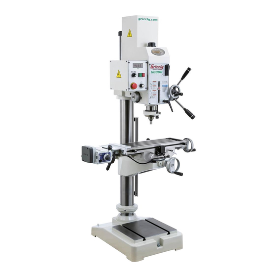
MODEL G0808
VARIABLE-SPEED GEARHEAD
DRILL PRESS w/CROSS-SLIDE TABLE
OWNER'S MANUAL
COPYRIGHT © MARCH, 2016 BY GRIZZLY INDUSTRIAL, INC.
WARNING: NO PORTION OF THIS MANUAL MAY BE REPRODUCED IN ANY SHAPE
OR FORM WITHOUT THE WRITTEN APPROVAL OF GRIZZLY INDUSTRIAL, INC.
#WK17932 PRINTED IN TAIWAN
V1.03.16
Advertisement
Table of Contents

Related Manuals for Grizzly G0808


Summary of Contents for Grizzly G0808
- Page 1 DRILL PRESS w/CROSS-SLIDE TABLE OWNER'S MANUAL COPYRIGHT © MARCH, 2016 BY GRIZZLY INDUSTRIAL, INC. WARNING: NO PORTION OF THIS MANUAL MAY BE REPRODUCED IN ANY SHAPE OR FORM WITHOUT THE WRITTEN APPROVAL OF GRIZZLY INDUSTRIAL, INC. #WK17932 PRINTED IN TAIWAN V1.03.16...
- Page 2 This manual provides critical safety instructions on the proper setup, operation, maintenance, and service of this machine/tool. Save this document, refer to it often, and use it to instruct other operators. Failure to read, understand and follow the instructions in this manual may result in fire or serious personal injury—including amputation, electrocution, or death.
-
Page 3: Table Of Contents
Table of Contents INTRODUCTION ..........2 SECTION 5: ACCESSORIES ......35 Contact Info............ 2 SECTION 6: MAINTENANCE ......38 Manual Accuracy ........... 2 Schedule ............38 Identification ........... 3 Cleaning & Protecting ........38 Controls & Components ......... 4 Lubrication ........... 39 Machine Data Sheet ........ -
Page 4: Introduction
ID label (see below). This information is required for us to provide proper tech support, and it helps us determine if updated documenta- tion is available for your machine. Manufacture Date Serial Number Model G0808 (Mfd. Since 11/15) -
Page 5: Identification
Fine Downfeed & Spindle Handwheel X-Axis Handwheel X-Axis Z-Axis Power Feed Crank Handle Cross Slide Z-Axis Y-Axis Power Feed Table Locks Handwheel To reduce your risk of serious injury, read this entire manual BEFORE using machine. Model G0808 (Mfd. Since 11/15) -
Page 6: Controls & Components
Twist clockwise to reset. O. Quill Lock: Locks quill in position. D. Spindle Speed Dial: Selects spindle speed Depth Scale: Indicates depth of cut. from 0–2500 RPM. E. ON/OFF Buttons: Starts and stops spindle rotation. Model G0808 (Mfd. Since 11/15) - Page 7 Master Power Switch: Toggles incoming power ON or OFF. Vertical position toggles incoming power ON. Horizontal position, (see Figure 5) toggles incoming power OFF. Note: Can be locked in OFF position with a padlock to prevent unauthorized usage. Model G0808 (Mfd. Since 11/15)
- Page 8 Power Feed Identification AA. Reset Button: Resets internal circuit breaker if unit is overloaded and shuts down. Model G0808 is equipped with power feed units for X- and Z-axis table movement. Refer to AB. Directional Lever: Selects direction of table Figures 6 and 7 and the following descriptions to movement.
-
Page 9: Machine Data Sheet
Machine Data Sheet MACHINE DATA SHEET Customer Service #: (570) 546-9663 · To Order Call: (800) 523-4777 · Fax #: (800) 438-5901 MODEL G0808 VARIABLE‐SPEED GEARHEAD DRILL PRESS WITH CROSS‐SLIDE TABLE Product Dimensions: Weight................................705 lbs. Width (side-to-side) x Depth (front-to-back) x Height............... 42 x 46-1/2 x 77-1/2 in. - Page 10 The information contained herein is deemed accurate as of 7/7/2016 and represents our most recent product specifications. Model G0808 PAGE 2 OF 2 Due to our ongoing improvement efforts, this information may not accurately describe items previously purchased. Model G0808 (Mfd. Since 11/15)
-
Page 11: Section 1: Safety
Everyday ery. Never operate under the influence of drugs or eyeglasses are NOT approved safety glasses. alcohol, when tired, or when distracted. Model G0808 (Mfd. Since 11/15) - Page 12 EXPERIENCING DIFFICULTIES. If at any time debris. Make sure they are properly installed, you experience difficulties performing the intend- undamaged, and working correctly BEFORE ed operation, stop using the machine! Contact our operating machine. Technical Support at (570) 546-9663. -10- Model G0808 (Mfd. Since 11/15)
-
Page 13: Additional Safety For Drill Presses
To avoid impact injuries, make sure complete stop before changing bits/cutting tools workpiece is free of nails or foreign objects in area or starting any inspection, adjustment, or mainte- to be drilled. nance procedure. -11- Model G0808 (Mfd. Since 11/15) -
Page 14: Section 2: Power Supply
To reduce the risk of these hazards, avoid over- loading the machine during operation and make sure it is connected to a power supply circuit that meets the specified circuit requirements. -12- Model G0808 (Mfd. Since 11/15) -
Page 15: Extension Cords
Minimum Gauge Size ......14 AWG all local codes and ordinances. Maximum Length (Shorter is Better)..50 ft. -13- Model G0808 (Mfd. Since 11/15) -
Page 16: Section 3: Setup
IMPORTANT: Save all packaging materials until you are completely satisfied with the machine and have resolved any issues between Grizzly or the shipping agent. You MUST have the original pack- aging to file a freight claim. It is also extremely helpful if you need to return your machine later. -
Page 17: Inventory
"-20 x 1 ⁄ " ......2 Flat Washers ⁄ " ......... 2 Slide Nuts ⁄ "-20......... 2 X-Axis Power Feed Hardware: Cap Screws M6-1 x 25 ....... 2 Flat Washers 6mm ........2 -15- Model G0808 (Mfd. Since 11/15) -
Page 18: Cleanup
Figure 12. T23692 Orange Power Degreaser. Repeat Steps 2–3 as necessary until clean, then coat all unpainted surfaces with a quality metal protectant to prevent rust. -16- Model G0808 (Mfd. Since 11/15) -
Page 19: Site Considerations
Shadows, glare, or strobe effects that may distract access restricted location. or impede the operator must be eliminated. Wall Min. 30" for Maintenance 46½" 42½" = Electrical Connection 56½" Illustration Not To Scale Figure 13. Minimum working clearances. -17- Model G0808 (Mfd. Since 11/15) -
Page 20: Lifting & Placing
With another person to help to steady machine, lift it just enough to clear pallet and any floor obstacles, then place it in its final position on shop floor. -18- Model G0808 (Mfd. Since 11/15) -
Page 21: Assembly
(if applicable). (see Figure 18). The Model G0808 ships with an extra X-axis handwheel and handle in case you choose not to install the X-axis power feed. If you choose not to install the X-axis power feed, skip those assembly... - Page 22 Cap Screws Bracket Assembly Power Feed Unit Left Side of Bracket Figure 21. X-axis power feed bracket assembly Assembly mounted to table. Figure 23. Left side of bracket assembly mounted to power feed unit. -20- Model G0808 (Mfd. Since 11/15)
- Page 23 Limit Switch 14. Remove adhesive backing from gear guard and install over X-axis table gear, as shown in Figure 25. Handle Figure 27. X-axis limit switch installed. Gear Guard Figure 25. Gear cover installed. -21- Model G0808 (Mfd. Since 11/15)
-
Page 24: Verify Lubrication
(Y-axis shown). Serious injury or death can result from using this machine BEFORE understanding its controls and related safety information. DO NOT operate, or allow others to operate, machine until the information is understood. -22- Model G0808 (Mfd. Since 11/15) - Page 25 Clear all setup tools away from machine. safety feature of the Emergency Stop but- ton is NOT working properly and must be Rotate Master Power Switch to ON ("1") replaced before further using the machine. position. -23- Model G0808 (Mfd. Since 11/15)
-
Page 26: Power Feed Test Run
Move direction lever to left, slowly turn speed dial clockwise to increase speed, then con- Model G0808 comes with power feed units for firm that table is moving to the left. X- and Z-axis table travel. Proper operation of the... -
Page 27: Spindle Break-In
Repeat Steps 2–3 with spindle speed dial set to "4" and "8" for 5 minutes in each direction. Set spindle speed range lever to high, then repeat Steps 2–4 at 5 minutes each. Congratulations, the Spindle Break-In is now complete! -25- Model G0808 (Mfd. Since 11/15) -
Page 28: Section 4: Operations
Firmly secures workpiece to table using a ects. Regardless of the content in this sec- vise or T-slot clamps. tion, Grizzly Industrial will not be held liable for accidents caused by lack of training. Adjusts table height, then locks it in place. -
Page 29: Master Power Switch
Vertical Elevation table movement is required. Unexpected (Up & Down) table and workpiece movement could cause Figure 34. The directions of table movement. tooling to bind with workpiece, which may damage tooling or workpiece. -27- Model G0808 (Mfd. Since 11/15) - Page 30 OFF, rotate speed dial all the way coun- terclockwise, and move direction lever to Z-Axis neutral (middle) position to avoid unexpected Limit Switch table movement later. Figure 38. Location of Z-axis limit switch and upper stop with stop bracket bolt. -28- Model G0808 (Mfd. Since 11/15)
-
Page 31: Head Tilt
When head is at 0°, re-insert index pin with hex nut, and gently tap it with a small hammer or mallet to seat it. Retighten lock nuts from Step 4. -29- Model G0808 (Mfd. Since 11/15) -
Page 32: Installing/Removing Tooling
Use wrench to tighten drawbar an additional Motor Cover ⁄ turn. Removed Note: overtighten drawbar. Overtightening makes tool removal difficult and may damage arbor and threads. Re-install motor cover. Figure 42. Motor cover removed. -30- Model G0808 (Mfd. Since 11/15) -
Page 33: Spindle Downfeed
Letting go of the levers too soon will Support tool with one hand and fully unthread cause the spindle to retract too quickly and slam drawbar from tool. up into the headstock. -31- Model G0808 (Mfd. Since 11/15) -
Page 34: Setting Depth Stop
It is not intended for tight-tolerance, precision results. To calibrate the depth stop see Calibrating Depth Stop on Page 43. Depth Stop Pointer Depth Stop Adjustment Knob Figure 47. Location of depth stop controls. -32- Model G0808 (Mfd. Since 11/15) -
Page 35: Spindle Speed
Also, there are a large number of easy-to-use spindle speed calculators that can be found on the internet. These sources will help you take into account the applicable variables in order to deter- mine the best spindle speed for the operation. -33- Model G0808 (Mfd. Since 11/15) -
Page 36: Calculating Spindle Speed For Drilling
Always clamp the Often, when drilling materials other than wood, workpiece to the table to prevent injuries. some type of lubrication is necessary. Figure 50. Drilling speed chart. -34- Model G0808 (Mfd. Since 11/15) -
Page 37: Section 5: Accessories
", letter bits from A–Z, and 60 number bits. serious personal injury or machine damage. Housed in a rugged steel case. To reduce this risk, only install accessories recommended for this machine by Grizzly. NOTICE Refer to our website or latest catalog for additional recommended accessories. - Page 38 T-slot clamps. T24799 T24800 Figure 57. Model T10440 Precision 3-Way Drill Figure 55. T24799 and T24800 Precision Press Vise. Parallel Blocks. www.grizzly.com 1-800-523-4777 order online at or call -36- Model G0808 (Mfd. Since 11/15)
- Page 39 Mats measure 36" x 36" x ⁄ ". Figure 59. H5611 V-Block Pair w/Clamps pictured. Figure 62. Model H6572 Grease-Resistant Mat 3' x 3' x ⁄ ". www.grizzly.com 1-800-523-4777 order online at or call -37- Model G0808 (Mfd. Since 11/15)
-
Page 40: Section 6: Maintenance
Lubrication section, beginning on Page 39. protection. • Check table movement in all three axis direc- tions for loose/tight gibs. Adjust the gibs if Keep tables rust-free with ISO 68 way oil. necessary (see Page 46). -38- Model G0808 (Mfd. Since 11/15) -
Page 41: Lubrication
Column X- and Y-Axis Leadscrews 40 Hrs. Rack Quill Rack and Pinion 90 Hrs. Power Feed Gears 160 Hrs. Figure 63. Recommended lubrication tasks, schedules, and instruction page references. Figure 65. Column and rack. -39- Model G0808 (Mfd. Since 11/15) -
Page 42: Headstock Reservoir
Run spindle at approximately 500 RPM for approximately 10 minutes to warm headstock oil. DISCONNECT MACHINE FROM POWER! Remove motor cover and fill plug (see Figure 66). Place drain pan on table under headstock. -40- Model G0808 (Mfd. Since 11/15) - Page 43 Re-install cover plate when finished. Note: Re-apply oil to the quill smooth outside surface that was removed during the cleaning Y-Axis process. Leadscrew Figure 69. Y-axis leadscrew as viewed from underneath knee. -41- Model G0808 (Mfd. Since 11/15)
-
Page 44: Power Feed Gears
Use rubbing alcohol or other appropriate sol- vent/cleaner to thoroughly clean grease/resi- Remove gear guard (see Figure 71). due from mating surfaces of gear guard, then re-install guard using double-sided adhesive tape. Gear Guard Figure 71. Location of gear guard. -42- Model G0808 (Mfd. Since 11/15) -
Page 45: Tensioning Return Spring
(see Figure 74). HOLD SPRING COVER TIGHTLY during this step, or force of spring will cause cover to spin out of your hands. Figure 75. Depth stop calibrated. -43- Model G0808 (Mfd. Since 11/15) -
Page 46: Section 7: Service
6. Tighten mounting bolts; relocate/shim machine. 7. Spindle bearings at fault. 7. Test by rotating spindle; rotational grinding/loose shaft requires bearing replacement. 8. Motor bearings at fault. 8. Test by rotating shaft; rotational grinding/loose shaft requires bearing replacement. -44- Model G0808 (Mfd. Since 11/15) -
Page 47: Power Feed
4. Motor shaft and gear shaft not engaged. 4. Replace clutch. Operates at high 1. Rapid traverse button at fault. 1. Inspect/replace rapid traverse button. speed only or is 2. Wiring harness unplugged from circuit 2. Reconnect wiring harness. inconsistent. board. -45- Model G0808 (Mfd. Since 11/15) -
Page 48: Adjusting Gibs
Loosen one gib adjustment screw, then tight- en the other the same amount to move the gib. Use handwheel/crank (if applicable) to move component until you feel a slight drag in the path of movement. Repeat Steps 3–4 as necessary. -46- Model G0808 (Mfd. Since 11/15) -
Page 49: Adjusting Leadscrew Backlash
Tool Needed X-Axis T-Handle Hex Wrench 5mm ......1 Leadscrew Nut Figure 78. X-axis leadscrew nut located under right side of table. Y-Axis Leadscrew Nut Screws Figure 79. Y-axis leadscrew nut located inside knee. -47- Model G0808 (Mfd. Since 11/15) -
Page 50: Tramming Spindle
Figure 81. Dial test indicator mounted. Dial Test Indicator (with at least 0.0005" resolution) ....1 Indicator Holder (mounted on the quill/spindle) ....1 Precision Parallel Block (at least 9" in length) ........1 -48- Model G0808 (Mfd. Since 11/15) - Page 51 Steps 6–7 until you are satisfied with the so the head does not move loosely while you spindle axis alignment along the table adjust it. Remember to tighten all the tilt lock X-axis. bolts after adjusting the head. -49- Model G0808 (Mfd. Since 11/15)
-
Page 52: Section 8: Wiring
Technical Support at (570) 546-9663. The photos and diagrams included in this section are best viewed in color. You can view these pages in color at www.grizzly.com. -50- Model G0808 (Mfd. Since 11/15) -
Page 53: Electrical Components
Figure 87. Electrical box wiring. Figure 84. Electrical component wiring overview. Z-Axis Limit Switch Z-Axis Power feed Figure 88. Control panel wiring. Figure 85. Z-axis power feed unit. READ ELECTRICAL SAFETY -51- Model G0808 (Mfd. Since 11/15) ON PAGE 50! -
Page 54: Wiring Diagram (Main)
NHD CB-10 CB-10 Master Power Switch Auspicious (Top View) 600V KEDU HY57B 12A 250V A60212 0249 Potentiometer Emergency Stop 6-15 Plug (As Recommended) Ground DRO Sensor DA-1805NO-3M 10-30VDC READ ELECTRICAL SAFETY -52- Model G0808 (Mfd. Since 11/15) ON PAGE 50! -
Page 55: Wiring Diagram (Power Feed)
VS10N021C 10A 125/250VAC wiring. BOTTOM HIGHLY VS10N021C 10A 125/250VAC Z-Axis Limit Switch Z-Axis Power Feed Unit Tiger 560s 110V 2.8A 110W Figure 89. Z-Axis limit switch ST-560 wiring. READ ELECTRICAL SAFETY -53- Model G0808 (Mfd. Since 11/15) ON PAGE 50! -
Page 56: Section 9: Parts
SECTION 9: PARTS We do our best to stock replacement parts when possible, but we cannot guarantee that all parts shown are available for purchase. Call (800) 523-4777 or visit www.grizzly.com/parts to check for availability. Headstock 1-20 1-21 54-1 54-2... -
Page 57: Headstock Parts List
LEVER HANDLE 1/2-13, 1-1/4 X 4-3/8 P0808021 LOCK WASHER 1/4 P0808067 LEVER SHAFT 1/2-13 X 3/4, 6-3/4L P0808022 FENDER WASHER 1/4 P0808068 HEADSTOCK ADAPTER COVER PLATE P0808023 CAP SCREW 1/4-20 X 5/8 P0808069 PHLP HD SCR 1/4-20 X 3/8 -55- Model G0808 (Mfd. Since 11/15) - Page 58 CHUCK ARBOR R8 X JT6 P0808092 CONTROL PANEL BOX P0808077 MOTOR COVER P0808093 RPM SENSOR DRH DA-1805NO-3M 10-30VDC P0808078 PHLP HD SCR M5-.8 X 8 P0808094 CONTROL PANEL COVER P0808079 RPM SENSOR BRACKET P0808095 STRAIN RELIEF TYPE-3 PG11 -56- Model G0808 (Mfd. Since 11/15)
-
Page 59: Gearbox
BALL BEARING 6202ZZ P0808130 COMPRESSION SPRING 0.8 X 7.1 X 15 P0808111 GEAR SHAFT ASSEMBLY 15T/41T P0808131 CAP SCREW M6-1 X 8 P0808115 STEEL BALL 5/16 P0808132 HEX NUT M6-1 P0808116 COMBO GEAR 16T/42T -57- Model G0808 (Mfd. Since 11/15) -
Page 60: Column
Column 207-2 207-1 207-3 216-4 207-3 216-5 207-1 207-2 216-6 216-1 216-2 216-3 216-2 232-1 232-2 232-3 232-5 232-2 232-4 206-1 206-2 232-6 206-5 206-3 206-4 -58- Model G0808 (Mfd. Since 11/15) -
Page 61: Column Parts List
P0808227 ADJUSTABLE HANDLE 2"L, 5/16-18 X 1-3/8 P0808272 POWER FEED UNIT ALIGN AL-500D P0808228 T-KNOB 5/16-18 X 1-5/8 P0808273 LIMIT SWITCH ALIGN DC2 P0808229 CAP SCREW 5/16-18 X 1 P0808274 X-AXIS LEADSCREW GEAR 56T -59- Model G0808 (Mfd. Since 11/15) -
Page 62: Z-Axis Power Feed
CAP SCREW M6-1 X 20 P0808339 CAP SCREW M6-1 X 15 P0808321 Z-AXIS CRANK HANDLE ASSEMBLY P0808340 LOCK WASHER 6MM 321-1 P0808321-1 HANDLE 2-3/4"L X 1"OD X 3/8"ID (PLASTIC) P0808341 LIMIT STOP BLOCK WASHER 8MM -60- Model G0808 (Mfd. Since 11/15) -
Page 63: Electrical
ON/OFF SWITCH NHD CB-10 22MM P0808403 GROUND TERMINAL 4P P0808408 ROTARY SWITCH NHD CB-10 22MM P0808404 CIRCUIT BOARD REV-A05 A57560 P0808409 POTENTIOMETER A60212 0249 P0808405 ROTARY SWITCH AUSP AC-21A 600V 20A P0808410 E-STOP KEDU HY57B 18A 125V/12A 250V -61- Model G0808 (Mfd. Since 11/15) -
Page 64: Labels
DO NOT REPRODUCE OR CHANGE THIS ARTWORK GRIZZLY GREEN PANTONE 568C GRIZZLY GREEN WITHOUT WRITTEN APPROVAL! Grizzly will not accept labels changed without approval. PANTONE 568C artwork changes are required, contact us immediately at manuals@grizzly.com. REFER TO COPYRIGHT © GRIZZLY INDUSTRIAL, INC. -
Page 65: Warranty Card
Would you recommend Grizzly Industrial to a friend? _____ Yes _____No Would you allow us to use your name as a reference for Grizzly customers in your area? Note: We never use names more than 3 times. _____ Yes _____No 10. - Page 66 FOLD ALONG DOTTED LINE Place Stamp Here GRIZZLY INDUSTRIAL, INC. P.O. BOX 2069 BELLINGHAM, WA 98227-2069 FOLD ALONG DOTTED LINE Send a Grizzly Catalog to a friend: Name_______________________________ Street_______________________________ City______________State______Zip______ TAPE ALONG EDGES--PLEASE DO NOT STAPLE...
-
Page 67: Warranty & Returns
WARRANTY & RETURNS Grizzly Industrial, Inc. warrants every product it sells for a period of 1 year to the original purchaser from the date of purchase. This warranty does not apply to defects due directly or indirectly to misuse, abuse, negligence, accidents, repairs or alterations or lack of maintenance.
Need help?
Do you have a question about the G0808 and is the answer not in the manual?
Questions and answers