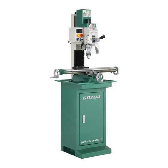
Grizzly G0704 Owner's Manual
Mill/drill with stand
Hide thumbs
Also See for G0704:
- Owner's manual (60 pages) ,
- Installation instructions manual (28 pages)
Table of Contents
Advertisement
For questions or help with this product contact Tech Support at (570) 546-9663 or techsupport@grizzly.com
The following changes were made to this machine since the owner's manual was printed:
•
Motor assembly changed—motor shaft is now 14mm OD.
•
Motor gear and ring changed to 14mm ID.
•
Added stand assembly parts breakdown and list.
Note: On the parts list, the new parts are designated with a "V2" or "V3".
Aside from this information, all other content in the owner's manual applies and MUST be read and under-
stood for your own safety. IMPORTANT: Keep this update with the owner's manual for future reference.
For questions or help, contact our Tech Support at (570) 546-9663 or techsupport@grizzly.com.
New Motor Assembly Parts
221V3
230V2
229V2
REF
PART #
DESCRIPTION
221V3
P0704221V3
MOTOR 1HP 110V (14MM SHAFT) V3.04.13
221-1V2 P0704221-1V2 CARBON BRUSH 1-PC V2.11.12
221-2V2 P0704221-2V2 CARBON BRUSH CAP 1-PC V2.11.12
229V2
P0704229V2
MOTOR GEAR RING (ID 14MM) V2.04.13
230V2
P0704230V2
GEAR 20T (ID 14MM) V2.04.13
231
P0704231
KEY 4 X 4 X 6
WARNING: NO PORTION OF THIS MANUAL MAY BE REPRODUCED IN ANY SHAPE
OR FORM WITHOUT THE WRITTEN APPROVAL OF GRIZZLY INDUSTRIAL, INC.
READ THIS FIRST
221-2V2
221-1V2
231
COPYRIGHT © JUNE, 2014 BY GRIZZLY INDUSTRIAL, INC.
#TS16629 PRINTED IN CHINA
Model G0704
***IMPORTANT UPDATE***
For Machines Mfd. Since April, 2013
& Owner's Manual Revised February, 2013
Stand Assembly Parts
100
100-2
100-3
REF
PART #
DESCRIPTION
100
P0704100
STAND ASSEMBLY
100-1
P0704100-1
STAND CABINET
100-2
P0704100-2
STAND DOOR
100-3
P0704100-3
STAND DOOR LATCH
100-1
Advertisement
Table of Contents

Related Manuals for Grizzly G0704


Summary of Contents for Grizzly G0704
- Page 1 STAND DOOR 100-3 P0704100-3 STAND DOOR LATCH COPYRIGHT © JUNE, 2014 BY GRIZZLY INDUSTRIAL, INC. WARNING: NO PORTION OF THIS MANUAL MAY BE REPRODUCED IN ANY SHAPE OR FORM WITHOUT THE WRITTEN APPROVAL OF GRIZZLY INDUSTRIAL, INC. #TS16629 PRINTED IN CHINA...
- Page 2 MODEL G0704 MILL/DRILL WITH STAND OWNER'S MANuAL Copyright © February, 2010 by grizzly industrial, inC. revised February, 2013 (tr) WARNING: NO pORTION Of THIS MANuAL MAy bE REpRODucED IN ANy SHApE OR fORM WITHOuT THE WRITTEN AppROvAL Of GRIzzLy INDuSTRIAL, INc.
- Page 3 This manual provides critical safety instructions on the proper setup, operation, maintenance, and service of this machine/tool. Save this document, refer to it often, and use it to instruct other operators. Failure to read, understand and follow the instructions in this manual may result in fire or serious personal injury—including amputation, electrocution, or death.
-
Page 4: Table Of Contents
Table of contents INTRODucTION ..........2 SEcTION 6: MAINTENANcE ......36 manual accuracy ........... 2 schedule ............36 Contact info............ 2 lubrication ........... 36 machine description ........2 SEcTION 7: SERvIcE ........39 identification ........... 3 troubleshooting ........... 39 electronic Controls identification ....4 gibs .............. -
Page 5: Introduction
Any updates to your model tionary on the table while the cutting tool moves of machine will be reflected in these documents up-and-down with the movement of the spindle as soon as they are complete. and head. Model G0704 (Mfg. Since 08/11) -
Page 6: Identification
H. longitudinal (X-axis) handwheel v. digital readout (page 4) longitudinal table stop W. Control panel (page 4) table Cross travel locks X. headstock K. table longitudinal travel lock y. Column table Center stop M. machine stand Model G0704 (Mfg. Since 08/11) -
Page 7: Electronic Controls Identification
Electronic controls Identification figure 2. g0704 electronic controls identification. G. in/mm unit selection button A. spindle rpm readout H. spindle depth display b. spindle digital readout oFF button spindle direction selection Knob c. digital readout on/zero button variable spindle speed Knob D. -
Page 8: Machine Data Sheet
MACHINE DATA SHEET Customer Service #: (570) 546-9663 · To Order Call: (800) 523-4777 · Fax #: (800) 438-5901 MODEL G0704 DRILL/MILL WITH STAND Product Dimensions: Weight................................265 lbs. Width (side-to-side) x Depth (front-to-back) x Height................38 x 24 x 31 in. - Page 9 The information contained herein is deemed accurate as of 3/3/2014 and represents our most recent product specifications. Model G0704 PAGE 2 OF 3 Due to our ongoing improvement efforts, this information may not accurately describe items previously purchased. Model G0704 (Mfg. Since 08/11)
- Page 10 The information contained herein is deemed accurate as of 3/3/2014 and represents our most recent product specifications. Model G0704 PAGE 3 OF 3 Due to our ongoing improvement efforts, this information may not accurately describe items previously purchased. Model G0704 (Mfg. Since 08/11)
-
Page 11: Section 1: Safety
Everyday ery. Never operate under the influence of drugs or eyeglasses are not approved safety glasses. alcohol, when tired, or when distracted. Model G0704 (Mfg. Since 08/11) - Page 12 ChILdREN & BYsTANdERs. Keepchildrenand cord/plugwithwethands.Avoidcorddamageby bystandersatasafedistancefromtheworkarea. keepingitawayfromheatedsurfaces,hightraffic Stopusingmachineiftheybecomeadistraction. areas,harshchemicals,andwet/damplocations. GuARds & COVERs.Guardsandcoversreduce EXPERIENCING dIFFICuLTIEs. If at any time accidental contact with moving parts or flying youexperiencedifficultiesperformingtheintend- debris. Make sure they are properly installed, edoperation,stopusingthemachine!Contactour undamaged,andworkingcorrectly. TechnicalSupportat(570)546-9663. Model G0704 (Mfg. Since 08/11)
-
Page 13: Additional Safety For Mill/Drills
No list of safety guidelines can be complete. Every shop environment is different. Like all machines there is danger associated with the Model G0704. Accidents are frequently caused by lack of familiarity or failure to pay attention. use this machine with respect and caution to lessen the possibility of operator injury. -
Page 14: Section 2: Power Supply
To reduce the risk of these hazards, avoid over- loading the machine during operation and make sure it is connected to a power supply circuit that meets the requirements in the following section. -11- Model G0704 (Mfg. Since 08/11) -
Page 15: Extension Cords
Two-prong outlets do not meet the grounding requirements for this machine. Do not modify or use an adapter on the plug provided—if it will not fit the outlet, have a qualified electrician install the proper outlet with a verified ground. -12- Model G0704 (Mfg. Since 08/11) -
Page 16: Section 3: Setup
(rated for at least 500 lbs.) ......1 • an assistant ..........1 unpacking The Model G0704 is a heavy machine. Serious personal injury may occur if safe moving meth- Your machine was carefully packaged for safe ods are not used. To be transportation. -
Page 17: Inventory
A. mill/drill w/stand ......... 1 figure 4. g0704 out of the crate. b. open end Combo Wrench 17/19 ....1 c. open end Combo Wrench 8/10 ....1 NOTICE D. -
Page 18: Cleanup
Repeat Steps 2–3 as necessary until clean, then coat all unpainted surfaces with a quality metal protectant to prevent rust. -15- Model G0704 (Mfg. Since 08/11) -
Page 19: Site Considerations
Shadows, glare, or strobe effects that may distract access restricted location. or impede the operator must be eliminated. Wall 30" 24" 25" 37.25" 57" figure 6. space required for full machine range of motion. -16- Model G0704 (Mfg. Since 08/11) -
Page 20: Moving & Placing Machine
The Model G0704 is a lift the machine and carefully place it onto heavy machine. Serious the stand. -
Page 21: Mounting To Shop Floor
Anchor studs are stronger and more per- manent alternatives to lag shield anchors; however, they will stick out of the floor, which may cause a tripping hazard if you decide to move your machine. -18- Model G0704 (Mfg. Since 08/11) -
Page 22: Assembly
Assembly Drill chuck Arbor assembly of the model g0704 consists of attach- your machine includes an b-16 drill chuck arbor ing the four handwheel handles to the machine. and drill chuck. before use, the drill chuck must be installed onto the arbor. the this drill chuck To assemble your machine: installation is intended to be semi-permanent. -
Page 23: Power Connection
1. Turn the machine power switch OFF. 2. Insert the power cord plug into a matching power supply receptacle. The machine is now connected to the power source. figure 16. Disconnecting power. figure 15. Connecting power. -20- Model G0704 (Mfg. Since 08/11) -
Page 24: Test Run & Spindle Break-In
— investigate and correct strange or unusual noises or vibrations before operating the the model g0704 spindle speed can be set from machine further. always disconnect the 50–2250 rpm. you must follow the proper break- machine from power when investigating or in procedures to ensure the spindle bearings correcting potential problems. -
Page 25: Section 4: Operations
Regardless of the content in this section, 11. turns the spindle direction knob to the "0" Grizzly Industrial will not be held liable for position to stop the spindle. accidents caused by lack of training. -
Page 26: Basic Controls
& drawbar fine feed Knob: provides fine control over verti- cal quill travel. Quill feed Levers: provide coarse control over Quill lock vertical quill travel. lever spindle & Chuck figure 19. headstock controls (continued). -23- Model G0704 (Mfg. Since 08/11) - Page 27 Spindle Speed Knob: Changes the speed of the spindle rotation. Spindle Direction Selection Knob: Changes the direction of spindle rotation. spindle rpm readout emergency stop button variable spindle speed Knob spindle direction selection Knob figure 21. Control panel. -24- Model G0704 (Mfg. Since 08/11)
-
Page 28: Digital Readout Unit
When the operation is complete, press the oFF button to conserve the battery. button battery Cover figure 23. digital readout controls. -25- Model G0704 (Mfg. Since 08/11) -
Page 29: Calculating Spindle Speed
24. Cutting speed table for hss cutting use the following formula to determine the tools. needed spindle rpm for your operation: (cutting Speed x 4) /Tool Diameter = RpM -26- Model G0704 (Mfg. Since 08/11) -
Page 30: Spindle Speed And Direction
the... -
Page 31: Spindle Height Controls
For maximum spindle rigidity when milling, it is better to keep the spindle retracted into the headstock as far as possible with the spindle lock and the downfeed selector knob tightened. -28- Model G0704 (Mfg. Since 08/11) -
Page 32: Drill Chuck
Drill chuck NOTICE The Model G0704 drawbar will extract the arbor from the spindle. Once the arbor or To install the drill chuck and arbor: collet has broken free from the spindle taper, be sure to properly support it while disConneCt mill/drill From poWer! continuing to loosen the drawbar. -
Page 33: Loading Tooling
Loading Tooling To remove the collet: disConneCt mill/drill From poWer! your model g0704 features an r-8 spindle taper, remove the drawbar cap. which gives the freedom to use standard r-8 cutting tools and collets. these optional collets lock the quill in place with the quill lock come in many sizes, typically ranging from ⁄... -
Page 34: Headstock Travel (Z-Axis And Rotation)
-31- Model G0704 (Mfg. Since 08/11) -
Page 35: Table Travel
0.100". the cross feed can be locked into position by a table lock lever located on the right side of the cross slide underneath the table (see figure 33). y-axis table lock levers figure 33. table locks and scales. -32- Model G0704 (Mfg. Since 08/11) -
Page 36: Section 5: Accessories
35. Worktable with angle. H8179—Horizontal Milling Table take advantage of the g0704 mill/drill 90° tilting G5684—R-8 vertical collet Rack headstock feature. install this lifted cast-iron hori- no more loose r-8 collets laying around in your zontal milling table for the correct clearance when tool box. - Page 37 39. model g8683z mini shop Fox ® components are added for vertical surfaces. mobile base. resists squeeze out, running, dripping and non- gumming. -34- Model G0704 (Mfg. Since 08/11)
- Page 38 -45 degrees to +45 degrees. figure 44. model g9849 indicator/base Combo table size: 5" x 7". figure 43. model g5758 tilt table. -35- Model G0704 (Mfg. Since 08/11)
-
Page 39: Section 6: Maintenance
38. protect other unpainted cast iron surfaces with regular applications of products like g96 ® figure 47. longitudinal way lube locations. treatment, slipit , or boeshield t-9. ® ® -36- Model G0704 (Mfg. Since 08/11) - Page 40 10. apply light machine oil to the exposed leadscrew threads, then move the table through its full range of longitudinal motion several times to disperse the oil along the full length of the leadscrew. -37- Model G0704 (Mfg. Since 08/11)
- Page 41 -38- Model G0704 (Mfg. Since 08/11)
-
Page 42: Section 7: Service
6. machine is incorrectly mounted or sits 6. tighten/replace mounting bolts in bench; relocate/ unevenly. shim machine. 7. motor bearings are at fault. 7. test by rotating shaft; rotational grinding/loose shaft requires bearing replacement. -39- Model G0704 (Mfg. Since 08/11) - Page 43 3. Check for proper cutting rotation for cutting tool. 4. Workpiece not securely clamped. 4. secure properly to the table. 5. spindle extended too far down. 5. Fully retract spindle and lower headstock. this increases rigidity. -40- Model G0704 (Mfg. Since 08/11)
-
Page 44: Gibs
-41- Model G0704 (Mfg. Since 08/11) -
Page 45: Leadscrew Backlash
58. battery replacement. of play when properly adjusted is 0.003"– 0.006". remove the old battery, dispose of it accord- ing to state and federal regulations, then replace it with a new one. replace the battery cover. -42- Model G0704 (Mfg. Since 08/11) -
Page 46: Motor Service
61. Installing new brush assembly. replace the brush cap to secure the brush in place. Cap screw (1 of 4) repeat for second brush assembly on the other side of the motor. figure 59. Removing motor cover. -43- Model G0704 (Mfg. Since 08/11) -
Page 47: Section 8: Wiring
Technical source. Support at (570) 546-9663. The photos and diagrams included in this section are best viewed in color. You can view these pages in color at www.grizzly.com. -44- Model G0704 (Mfg. Since 08/11) -
Page 48: Wiring Diagram
RPM Sensor Fuse Holder see figure 65 Circuit Board Motor Brushes Motor 110V 93ZYT-008 750W 60Hz RPM Display On/off Switch Spindle Speed Knob see figure 64 Spindle Direction Knob READ ELECTRICAL SAFETY -45- Model G0704 (Mfg. Since 08/11) ON PAGE 44! -
Page 49: Electrical Components
Electrical components figure 62. Rear panel. figure 64. Control panel wiring. figure 63. Chip guard limit switch. figure 65. Side panel. READ ELECTRICAL SAFETY -46- Model G0704 (Mfg. Since 08/11) ON PAGE 44! -
Page 50: Section 9: Parts
SEcTION 9: pARTS column breakdown 31-1 34 35 36 37 14 15 -47- Model G0704 (Mfg. Since 08/11) -
Page 51: Column Parts List
COLUMN TOP PLATE P0704074 X-AXIS BEARING HOUSING P0704035 COLLAR FLANGE P0704075 X-AXIS LEADSCREW P0704036 CAP SCREW M5-.8 X 12 P0704076 BASE P0704037 Z-AXIS GRADUATED DIAL P0704077 CAP SCREW M12-1.75 X 90 P0704038 Z-AXIS HANDWHEEL -48- Model G0704 (Mfg. Since 08/11) -
Page 52: Electrical Box Breakdown & Parts List
CAP SCREW M4-.7 X 10 P0704094 STRAIN RELIEF M20 X 1.5 TYPE-3 P0704085 CONTROL PANEL PLATE P0704095 FWD/REV SWITCH KEDU EN61058 P0704086 CAP SCREW M4-.7 X 6 P0704096 FUSE 10A 250V FAST-ACTING GLASS P0704087 RPM DIGITIAL DISPLAY ZD-SX-THL -49- Model G0704 (Mfg. Since 08/11) -
Page 53: Headstock Breakdown
Headstock breakdown 206-2 220V2 206-1 221-2V2 209-2 221-1V2 209-1 221V2 225-2 225-1 216 217 218 234-1 234-2 272 271 246-2 246-1 246V2 255-1 -50- Model G0704 (Mfg. Since 08/11) -
Page 54: Headstock Parts List
WRENCH 17 X 19MM OPEN-ENDS P0704239 HEADSTOCK REAR COVER P0704408 SCREWDRIVER FLAT #2 P0704240 CAP SCREW M4-.7 X 8 P0704409 SCREWDRIVER PHILLIPS #2 P0704241 FINE FEED KNOB P0704410 BOTTLE FOR OIL P0704242 HEADSTOCK FRONT COVER P0704411 TOOLBOX -51- Model G0704 (Mfg. Since 08/11) -
Page 55: Chip Guard Breakdown & Parts List
EXT RETAINING RING 12MM P0704287 CHIP GUARD POST P0704281 WAVY WASHER 20MM P0704288 CHIP GUARD P0704282 GUARD MOUNTING BLOCK P0704289 CAP SCREW M4-.7 X 18 P0704283 SPACER, COPPER P0704290 CAP SCREW M3-.5 X 16 -52- Model G0704 (Mfg. Since 08/11) -
Page 56: Labels Breakdown & Parts List
MuST maintain the original location and readability of the labels on the machine. If any label is removed or becomes unreadable, REpLAcE that label before using the machine again. contact Grizzly at (800) 523-4777 or www.grizzly.com to order new labels. -53- Model G0704 (Mfg. Since 08/11) - Page 57 NOTES -54- Model G0704 (Mfg. Since 08/11)
-
Page 58: Warranty Card
Do you think your machine represents a good value? _____ Yes _____No Would you recommend Grizzly Industrial to a friend? _____ Yes _____No Would you allow us to use your name as a reference for Grizzly customers in your area? Note: We never use names more than 3 times. - Page 59 FOLD ALONG DOTTED LINE Place Stamp Here GRIZZLY INDUSTRIAL, INC. P.O. BOX 2069 BELLINGHAM, WA 98227-2069 FOLD ALONG DOTTED LINE Send a Grizzly Catalog to a friend: Name_______________________________ Street_______________________________ City______________State______Zip______ TAPE ALONG EDGES--PLEASE DO NOT STAPLE...
-
Page 60: Warranty And Returns
WARRANTY AND RETURNS Grizzly Industrial, Inc. warrants every product it sells for a period of 1 year to the original purchaser from the date of purchase. This warranty does not apply to defects due directly or indirectly to misuse, abuse, negligence, accidents, repairs or alterations or lack of maintenance.
Need help?
Do you have a question about the G0704 and is the answer not in the manual?
Questions and answers