Table of Contents
Advertisement
Quick Links
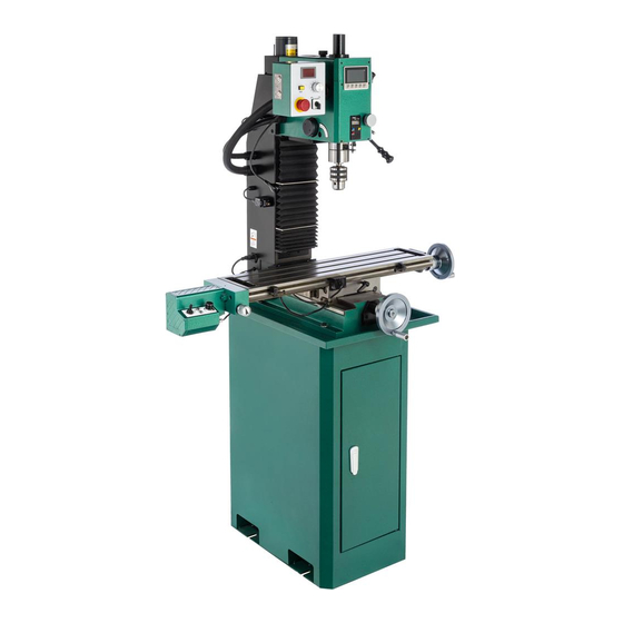
MODEL G0935
1-1/2 HP MILL/DRILL
w/POWER HEAD & STAND
OWNER'S MANUAL
(For models manufactured since 04/21)
COPYRIGHT © SEPTEMBER, 2021 BY GRIZZLY INDUSTRIAL, INC.
WARNING: NO PORTION OF THIS MANUAL MAY BE REPRODUCED IN ANY SHAPE
OR FORM WITHOUT THE WRITTEN APPROVAL OF GRIZZLY INDUSTRIAL, INC.
#AICS21883 PRINTED IN CHINA
V1.09.21
Advertisement
Table of Contents

Related Manuals for Grizzly G0935


Summary of Contents for Grizzly G0935
- Page 1 (For models manufactured since 04/21) COPYRIGHT © SEPTEMBER, 2021 BY GRIZZLY INDUSTRIAL, INC. WARNING: NO PORTION OF THIS MANUAL MAY BE REPRODUCED IN ANY SHAPE OR FORM WITHOUT THE WRITTEN APPROVAL OF GRIZZLY INDUSTRIAL, INC. #AICS21883 PRINTED IN CHINA V1.09.21...
- Page 2 This manual provides critical safety instructions on the proper setup, operation, maintenance, and service of this machine/tool. Save this document, refer to it often, and use it to instruct other operators. Failure to read, understand and follow the instructions in this manual may result in fire or serious personal injury—including amputation, electrocution, or death.
-
Page 3: Table Of Contents
Table of Contents INTRODUCTION ..........2 SECTION 6: MAINTENANCE ......36 Contact Info............ 2 Schedule ............36 Manual Accuracy ........... 2 Cleaning and Protecting ......36 Identification ........... 3 Lubrication ........... 37 Controls & Components ......... 4 Replacing Spindle Depth DRO Battery ..38 Machine Data Sheet ........ -
Page 4: Introduction
Always consider safety first, as it applies to your individual working conditions. Use this and other machinery with caution and respect. Failure to do so could result in serious personal injury, damage to equip- ment, or poor work results. Model G0935 (Mfd. Since 04/21) -
Page 5: Identification
Q. X-Axis Lock Handle G. Coarse Downfeed Handle R. Power Feed Limit Switch H. Downfeed Selector Handle S. Leadscrew Selector Knob X-Axis Power Feed and Controls Chuck U. LED Worklight Spindle Depth DRO K. Spindle V. Quill Lock Model G0935 (Mfd. Since 04/21) -
Page 6: Controls & Components
: Press to toggle between mm and inches. : Press to toggle between absolute or rela- tive measurement for selected axis. : Button has no function on this machine. : Press to change selected axis. Model G0935 (Mfd. Since 04/21) - Page 7 0. P. Coarse Downfeed Handle: Pull down for fast spindle downfeed with drilling operations; features spring-loaded spindle return. Q. Downfeed Selector Handle: Rotate to engage fine spindle control for milling operations. Model G0935 (Mfd. Since 04/21)
-
Page 8: Machine Data Sheet
MACHINE DATA SHEET Customer Service #: (570) 546-9663 · To Order Call: (800) 523-4777 · Fax #: (800) 438-5901 MODEL G0935 7" X 29" 1‐1/2 HP MILL/DRILL WITH POWER MODEL G0935 HEAD ELEVATION AND DRO 1-1/2 HP MILL/DRILL W/POWER HEAD & STAND Product Dimensions: Weight................................ - Page 9 The information contained herein is deemed accurate as of 9/28/2021 and represents our most recent product specifications. Model G0935 PAGE 2 OF 3 Due to our ongoing improvement efforts, this information may not accurately describe items previously purchased. Model G0935 (Mfd. Since 04/21)
- Page 10 The information contained herein is deemed accurate as of 9/28/2021 and represents our most recent product specifications. Model G0935 PAGE 3 OF 3 Due to our ongoing improvement efforts, this information may not accurately describe items previously purchased. Model G0935 (Mfd. Since 04/21)
-
Page 11: Section 1: Safety
Never operate under the influence of drugs or injury or blindness from flying particles. Everyday alcohol, when tired, or when distracted. eyeglasses are NOT approved safety glasses. Model G0935 (Mfd. Since 04/21) - Page 12 Make sure they are properly installed, you experience difficulties performing the intend- undamaged, and working correctly BEFORE ed operation, stop using the machine! Contact our operating machine. Technical Support at (570) 546-9663. -10- Model G0935 (Mfd. Since 04/21)
-
Page 13: Additional Safety For Mill/Drills
OFF to avoid a possible sudden startup use. This will prevent them from being thrown by once power is restored. the spindle upon startup. -11- Model G0935 (Mfd. Since 04/21) -
Page 14: Section 2: Power Supply
-12- Model G0935 (Mfd. Since 04/21) - Page 15 Two-prong outlets do not meet the grounding requirements for this machine. Do not modify or use an adapter on the plug provided—if it will not fit the outlet, have a qualified electrician install the proper outlet with a verified ground. -13- Model G0935 (Mfd. Since 04/21)
-
Page 16: Section 3: Setup
IMPORTANT: Save all packaging materials until you are completely satisfied with the machine and have resolved any issues between Grizzly or the shipping agent. You MUST have the original pack- aging to file a freight claim. It is also extremely helpful if you need to return your machine later. -
Page 17: Inventory
N. Fuse 2A 250V ..........1 O. Fuse 20A 250V ........... 1 Hex Wrench Set 3, 4, 5, 6mm ....1 Q. Spindle Spanner Wrench ......1 Figure 7. G0935 inventory. R. Handwheel Handles ........2 -15- Model G0935 (Mfd. Since 04/21) -
Page 18: Cleanup
Figure 8. T23692 Orange Power Degreaser. Repeat Steps 2–3 as necessary until clean, then coat all unpainted surfaces with a quality metal protectant to prevent rust. -16- Model G0935 (Mfd. Since 04/21) -
Page 19: Site Considerations
Only install in an Shadows, glare, or strobe effects that may distract access restricted location. or impede the operator must be eliminated. Wall Min. 30" for Maintenance 32" " 61" Figure 9. Minimum working clearances. -17- Model G0935 (Mfd. Since 04/21) -
Page 20: Lifting & Placing
Machine Base Lag Shield Anchor Concrete Drilled Hole Figure 11. Popular method for anchoring machinery to a concrete floor. Figure 10. Lifting sling used to lift G0935. Use forklift to move machine to final location. -18- Model G0935 (Mfd. Since 04/21) -
Page 21: Assembly
To connect machine to power: The Model G0935 comes nearly fully assembled from the factory; however, the handwheel handles Press E-STOP button (see Figure 13). for the table need to be installed. Before use, thread X- and Y-axis handles into handwheels, as shown in Figure 12. -
Page 22: Test Run
To test run machine: Clear all setup tools away from machine. Make sure cables and cords are well clear of table movement and potential direction of Figure 16. Resetting E-STOP button. travel. -20- Model G0935 (Mfd. Since 04/21) - Page 23 Safety feature of E-STOP button is NOT 17. Read Controlling Table Travel section, working properly and must be replaced beginning on Page 27, to understand function before further using machine. of power feed, table locks, and limit stops. -21- Model G0935 (Mfd. Since 04/21)
- Page 24 28. Flip direction switch through neutral (middle) position and all the way to the right. Turn speed control dial clockwise to turn power feed ON. Table should begin moving to the right. -22- Model G0935 (Mfd. Since 04/21)
-
Page 25: Spindle Bearing Break-In
5 minutes in been sitting idle for longer than 6 months. each direction of rotation at each speed. -23- Model G0935 (Mfd. Since 04/21) -
Page 26: Section 4: Operations
Regardless of the content in this sec- tion, Grizzly Industrial will not be held liable for accidents caused by lack of training. -24- Model G0935 (Mfd. Since 04/21) -
Page 27: Using Spindle Downfeed
DRO for precise movement. D. Downfeed Selector Handle. Tighten to use spindle with fine downfeed knob. Loosen to use spindle with coarse downfeed handles. E. Coarse Downfeed Handle. Manually con- trols quick spindle downfeed. -25- Model G0935 (Mfd. Since 04/21) - Page 28 Tighten downfeed selector handle (see complete to conserve battery. Figure 24) to engage fine downfeed knob. Loosen quill lock with quill lock lever. Rotate fine downfeed knob clockwise and lower cutting tool so it just touches workpiece. -26- Model G0935 (Mfd. Since 04/21)
-
Page 29: Controlling Table Travel
Y-Axis Handwheel There is no separate power switch for the power feed. Make sure power cords and other wires do not interfere with table movement. Y-Axis X-Axis Table Lock Table Lock Figure 27. Y-axis controls. -27- Model G0935 (Mfd. Since 04/21) -
Page 30: Adjusting Headstock
Fault Indicator The headstock can be adjusted up and down the Switch Light column (Z-axis). The G0935 has a dovetailed slide that allows users to reposition the headstock or change tooling without losing workpiece align- Figure 29. Table power feed controls. -
Page 31: Joining New Drill Chuck & Arbor
Spindle Spanner Wrench ........1 Figure 31. Tapping drill chuck/arbor on block of Brass-Head or Dead-Blow Hammer ....1 wood. Attempt to separate drill chuck and arbor by hand —if they separate, repeat Steps 3–4. -29- Model G0935 (Mfd. Since 04/21) - Page 32 With one hand holding tool in place, insert Figure 34. Using hex wrench and spindle drawbar into spindle from top of headstock, spanner wrench to loosen drawbar. then thread it into tool by hand until snug. -30- Model G0935 (Mfd. Since 04/21)
-
Page 33: Setting Spindle Speed
Setting Spindle Speed Range ing tool life. The Model G0935 has two spindle speed ranges: To set the spindle speed for your operation, you a low speed range that spans from 80–1700... - Page 34 Spindle Pulley Figure 39. Belt configuration chart. Pulley IMPORTANT: Model G0935 ships with high Figure 41. Correct belt deflection. speed range belt installed. Belt for low speed range is smaller than high speed range belt When belt has been tensioned correctly, and has teeth to engage upper pulleys.
-
Page 35: Section 5: Accessories
® serious personal injury or machine damage. easy-to-read 0°–360° scales. To reduce this risk, only install accessories recommended for this machine by Grizzly. NOTICE Refer to our website or latest catalog for additional recommended accessories. H7576—Precision Self-Centering Vise Figure 44. - Page 36 (included) and comes with an R8 arbor. It takes a Protected in a vinyl pouch. ⁄ "-20 drawbar. Figure 47. G5680 Adjustable Parallel Set. Figure 49. G2861 Face Mill. www.grizzly.com 1-800-523-4777 order online at or call -34- Model G0935 (Mfd. Since 04/21)
- Page 37 Figure 53. Recommended products for protect- ing unpainted cast iron/steel parts on machinery. Figure 51. T26419 Syn-O-Gen Synthetic Grease. www.grizzly.com 1-800-523-4777 order online at or call -35- Model G0935 (Mfd. Since 04/21)
-
Page 38: Section 6: Maintenance
Keep unpainted cast-iron surfaces rust-free and fix the problem before continuing operations: with regular applications a quality metal protectant (see Page 35 for offerings from Grizzly). • Loose mounting bolts. •... -
Page 39: Lubrication
Use clean brush to wipe leadscrew teeth with recommended lubrication, then move components back and forth several times over Figure 54. Location of Z-axis way cover and full range of travel to spread lubricant and ensure ways. smooth movement. -37- Model G0935 (Mfd. Since 04/21) -
Page 40: Replacing Spindle Depth Dro Battery
Stiff Brush ............2 T26419 or NLGI#2 Equivalent ... As Needed Replace battery cover. To lubricate quill rack: Lower quill to gain full access to quill rack (see Figure 57). Lock in position. -38- Model G0935 (Mfd. Since 04/21) -
Page 41: Section 7: Service
1. USB not plugged in at column circuit board or 1. Check USB connections. does not control panel port. illuminate. 2. LED burned out. 2. Replace LED. 3. Wiring broken, disconnected, or corroded. 3. Fix broken wires or disconnected/corroded connections. -39- Model G0935 (Mfd. Since 04/21) - Page 42 3. Wiring broken, disconnected, or corroded. 3. Fix broken wires or disconnected/corroded connections. 4. Z-axis limit switch(es) at fault. 4. Replace limit switch(es). 5. Z-axis jog button(s) at fault 5. Replace jog button(s). -40- Model G0935 (Mfd. Since 04/21)
- Page 43 2. Center cutting tool. 3. Chip packing. 3. Use spiral point/spiral fluted taps; reduce number of flutes to provide extra chip room. 4. Galling (adhesion between surfaces). 4. Use proper cutting fluid; reduce tapping speed. -41- Model G0935 (Mfd. Since 04/21)
- Page 44 Speed will not 1. Speed dial stripped. 1. Replace dial. adjust or is 2. Wiring broken, disconnected, or corroded. 2. Fix broken wires or disconnected/corroded inconsistent. connections. 3. Potentiometer at fault. 3. Test/replace potentiometer. -42- Model G0935 (Mfd. Since 04/21)
-
Page 45: Adjusting Gibs
Z-axis way cover in place (see Figure 61). X-Axis Gib (Right) Y-Axis Gib (Front) Figure 59. Location of front-right gib screws. Figure 61. Example of locations of Z-axis cover Phillips head screws. Loosen Z-axis lock handle. -43- Model G0935 (Mfd. Since 04/21) -
Page 46: Adjusting Leadscrew Backlash
Disconnect power and repeat Steps 3–4. Install top of Z-axis way cover with screws Y-Axis removed in Step 1. Leadscrew Nut Tighten Z-axis lock handle. Figure 63. Location of leadscrew nuts. -44- Model G0935 (Mfd. Since 04/21) -
Page 47: Replacing Brushes
Remove belt from pulleys (see Figure 65). Items Needed Hex Wrench 4mm ..........1 Flat Head Screwdriver " ......... 1 Replacement Brush Pair (P0935099) ....1 Belt Figure 65. Location of belt tension cap screws. -45- Model G0935 (Mfd. Since 04/21) - Page 48 Items Needed Phillips Head Screwdriver #2 ......1 Install power feed motor (if removed). Penny or Dime ........... 1 Replacement Brush Pair (P0935353-3) .... 1 Install power feed side and bottom covers. -46- Model G0935 (Mfd. Since 04/21)
-
Page 49: Section 8: Wiring
Technical Support at (570) 546-9663. The photos and diagrams included in this section are best viewed in color. You can view these pages in color at www.grizzly.com. -47- Model G0935 (Mfd. Since 04/21) -
Page 50: Main Wiring Overview
3-Axis DRO Spindle Speed Upper Z-Axis Sensor Limit Switch Headstock Cover Lower Z-Axis Limit Switch Limit Switch X-Axis Sensor Neutral Z-Axis Sensor 110 VAC Y-Axis Sensor 5-15 Plug Ground READ ELECTRICAL SAFETY -48- Model G0935 (Mfd. Since 04/21) ON PAGE 47! -
Page 51: Control Panel Wiring
Fault Light LAS3 Potentiometer Spindle Motor Spindle Speed DRO (Inside Headstock) RSD-27 Control Panel Cover Figure 71. Spindle speed sensor and spindle motor. Spindle Motor Spindle Speed Sensor READ ELECTRICAL SAFETY -49- Model G0935 (Mfd. Since 04/21) ON PAGE 47! -
Page 52: Column Wiring
Column Power Connection DC1 DC2 AC3 AC4 8 P1 P2 P3 Socket Plug Circuit Board 5-15P D6-14F WGPCB FC-1100BJ/110V 20A 250V Fuse Ground Figure 73. Lower column wiring. READ ELECTRICAL SAFETY -50- Model G0935 (Mfd. Since 04/21) ON PAGE 47! -
Page 53: Z-Axis Motor & Limit Switch Wiring
Upper Z-Axis Limit Switch KEDU QKS7 (To Column) Figure 75. Upper Z-axis limit switch wiring. Lower Z-Axis Limit Switch KEDU QKS7 (To Column) Figure 76. Lower Z-axis limit switch wiring. READ ELECTRICAL SAFETY -51- Model G0935 (Mfd. Since 04/21) ON PAGE 47! -
Page 54: 3-Axis Dro & Sensors Wiring
Figure 78. X- and Y-axis sensors. Z-Axis Sensor Figure 77. 3-axis DRO and spindle depth DRO wiring. Figure 79. Z-axis sensor. 3-Axis DRO X-Axis Sensor MG10V (To Column) Y-Axis Sensor Z-Axis Sensor READ ELECTRICAL SAFETY -52- Model G0935 (Mfd. Since 04/21) ON PAGE 47! -
Page 55: Headstock Cover Safety Switch & Led Worklight Wiring
& LED Worklight Wiring Headstock Cover Safety Switch KEDU QKS8 (To Spindle Control Panel) Figure 80. Headstock cover safety switch wiring. LED Worklight USB Plug Figure 81. LED worklight wiring. READ ELECTRICAL SAFETY -53- Model G0935 (Mfd. Since 04/21) ON PAGE 47! -
Page 56: Power Feed Wiring Overview
X-Axis Limit Switches (Page 55) X-Axis X-Axis Power Feed (Page 55) Power Feed Limit Switches Figure 83. X-axis limit switch wiring. Figure 82. Power feed box wiring (as viewed from bottom). READ ELECTRICAL SAFETY -54- Model G0935 (Mfd. Since 04/21) ON PAGE 47! -
Page 57: Power Feed Wiring
OMRON SS-5GL Direction Switch Potentiometer KEDU HY29K Fault Light WH24-2 F4K7 Power Light P1 P2 P3 Power Adapter Socket Circuit Board WGPCB 1552 Power Feed Box Bottom Cover READ ELECTRICAL SAFETY -55- Model G0935 (Mfd. Since 04/21) ON PAGE 47! -
Page 58: Section 9: Parts
SECTION 9: PARTS We do our best to stock replacement parts when possible, but we cannot guarantee that all parts shown are available for purchase. Call (800) 523-4777 or visit www.grizzly.com/parts to check for availability. Headstock 92 92 BUY PARTS ONLINE AT GRIZZLY.COM! -56- Model G0935 (Mfd. - Page 59 PHLP HD SCR M4-.7 X 8 P0935049 MOTOR PULLEY, LOW SPEED P0935099 CARBON BRUSHES (PAIR) P0935050 OUTPUT SHAFT CAP 100 P0935100 BRUSH CAP BUY PARTS ONLINE AT GRIZZLY.COM! -57- Model G0935 (Mfd. Since 04/21) Scan QR code to visit our Parts Store.
-
Page 60: Column
Column 154 157 BUY PARTS ONLINE AT GRIZZLY.COM! -58- Model G0935 (Mfd. Since 04/21) Scan QR code to visit our Parts Store. - Page 61 P0935122 MOTOR W/GEARBOX 25W 110V 1-PH 4GN-18K P0935186 PHLP HD SCR M4-.7 X 10 P0935123 CAP SCREW M6-1 X 20 P0935187 Y-AXIS WAY COVER BUY PARTS ONLINE AT GRIZZLY.COM! -59- Model G0935 (Mfd. Since 04/21) Scan QR code to visit our Parts Store.
-
Page 62: Cabinet & Controls
HEX NUT M4-.7 THIN P0935225 SPINDLE SPEED SENSOR ASSEMBLY SIEG P0935254 TERMINAL BAR 4P P0935226 SPINDLE SPEED SENSOR BRACKET P0935255 FUSE HOLDER BUY PARTS ONLINE AT GRIZZLY.COM! -60- Model G0935 (Mfd. Since 04/21) Scan QR code to visit our Parts Store. -
Page 63: Table
Table 353-1 353-2 367 368 329 330 344 345 BUY PARTS ONLINE AT GRIZZLY.COM! -61- Model G0935 (Mfd. Since 04/21) Scan QR code to visit our Parts Store. - Page 64 P0935342 Y-AXIS LEADSCREW M16-2.5 X 280 P0935397 PHLP HD SCR M4-.7 X 8 P0935343 HANDWHEEL TYPE-8 130D X 10B X M8-1 BUY PARTS ONLINE AT GRIZZLY.COM! -62- Model G0935 (Mfd. Since 04/21) Scan QR code to visit our Parts Store.
-
Page 65: Stand & Accessories
HEX WRENCH SET (4-PC) P0935409 OIL BOTTLE P0935420 SPINDLE SPANNER WRENCH P0935410 T-NUT M12-1.75 P0935421 DRILL CHUCK JT6 X 1-16MM P0935411 QUILL LOCK LEVER BUY PARTS ONLINE AT GRIZZLY.COM! -63- Model G0935 (Mfd. Since 04/21) Scan QR code to visit our Parts Store. -
Page 66: Labels & Cosmetics
Safety labels help reduce the risk of serious injury caused by machine hazards. If any label comes off or becomes unreadable, the owner of this machine MUST replace it in the original location before resuming operations. For replacements, contact (800) 523-4777 or www.grizzly.com. BUY PARTS ONLINE AT GRIZZLY.COM! -64- Model G0935 (Mfd. -
Page 67: Warranty & Returns
WARRANTY & RETURNS Grizzly Industrial, Inc. warrants every product it sells for a period of 1 year to the original purchaser from the date of purchase. This warranty does not apply to defects due directly or indirectly to misuse, abuse, negligence, accidents, repairs or alterations or lack of maintenance.
Need help?
Do you have a question about the G0935 and is the answer not in the manual?
Questions and answers