
Related Manuals for Grizzly G0520


Summary of Contents for Grizzly G0520
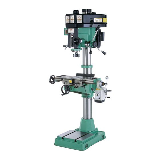
- Page 1 MODEL G0520 DRILL PRESS w/POWER FEED & CROSS SLIDE TABLE OWNER'S MANUAL WARNING: NO PORTION OF THIS MANUAL MAY BE REPRODUCED IN ANY SHAPE OR FORM WITHOUT THE WRITTEN APPROVAL OF GRIZZLY INDUSTRIAL, INC.
-
Page 3: Table Of Contents
INTRODUCTION ... 2 SECTION 1: SAFETY ... 6 SECTION 2: CIRCUIT REQUIREMENTS ... 9 SECTION 3: SETUP ... 10 SECTION 4: OPERATIONS ... 17 Table of Contents SECTION 5: ACCESSORIES ... 28 SECTION 6: MAINTENANCE ... 30 SECTION 7: SERVICE ... 34 SECTION 8: PARTS ... -
Page 4: Introduction
INTRODUCTION Manual Accuracy Functional Overview your machine may not exactly match the manual www.grizzly.com Contact Info... - Page 5 Identification Figure 1. Feed Power Page 23...
-
Page 6: Machine Data Sheet
Machine Data Sheet Customer Service #: (570) 546-9663 · To Order Call: (800) 523-4777 · Fax #: (800) 438-5901 MODEL G0520 DRILL PRESS W/ CROSS SLIDING TABLE & Product Dimensions: Weight... 672 lbs. Length/Width/Height... 39 x 37-1/4 x 74-3/8 in. - Page 7 Drilling Capacity...1-1/4 in. in Mild Steel No Of Spindle Speeds...12 Range Of Spindle Speeds... 140 - 2570 RPM Drill Chuck Type... JT3 Key Chuck Drill Chuck Size... 5/8 in. End Milling Cap...7/8 in. in Mild Steel Face Milling Cap... 3 in. in Mild Steel Other Specifications: Country Of Origin ...
-
Page 8: Safety Instructions For Machinery
Safety Instructions for Machinery... -
Page 10: Additional Safety Instructions For Drill Presses
Additional Safety Instructions for Drill EYE/FACE/HAND PROTECTION. DRILL BIT. CHUCK KEYS & TOOLS. WORKPIECE MATERIAL. DAMAGED TOOLS. OPERATING SPEED. Like all machinery there is potential danger when operating this machine. Accidents are fre- quently caused by lack of familiarity or failure to pay attention. Use this machine with respect and caution to decrease the risk of operator injury. -
Page 11: Section 2: Circuit Requirements
SECTION 2: CIRCUIT REQUIREMENTS 220V Operation Serious personal injury could occur if you connect the machine to power before com- pleting the setup process. DO NOT connect the machine to the power until instructed later in this manual. Electrocution or fire could result if machine is not grounded and installed in compliance with electrical... -
Page 12: Section 3: Setup
Wear safety glasses dur- ing the entire setup pro- cess! The Model G0520 is a heavy machine. Serious personal occur if safe moving methods are not used. To be safe, get assistance... - Page 13 Inventory Note: If you can't find an item on this list, check the mounting location on the machine or examine the packaging materials carefully. Occasionally we pre-install certain components for shipping purposes. Inventory: (Figure 3) Figure 3. SUFFOCATION HAZARD! Immediately discard all plas- tic bags and packing materi- als to eliminate choking/suf- focation hazards for children...
-
Page 14: Site Considerations
Lock entrances to the shop or disable start switch or power connection to prevent unsupervised use. Moving & Placing Base Unit The Model G0520 is a heavy machine. Serious personal occur if safe moving methods are not used. To be safe, get assistance... -
Page 15: Mounting To Shop Floor
Figure 7 Note: Make sure the 2x4 behind the column is not resting on the motor fan cover to avoid damaging it when lifting the machine. Figure 7. Mounting to Shop Floor Bolting to Concrete Floors Figure 8 Figure 8... - Page 16 Assembly Tools Needed To assemble your drill press: Figure 9 Figure 9. Figure 10. Figure 11. Figure 10 Figure...
-
Page 17: Test Run
Figure 12 Figure 12. Test Run Troubleshooting Page 34 To test run the machine: Figure 13. Figure 13... -
Page 18: Spindle Break-In
Feed Page 23 Test Run Break-In Spindle Break-In Successfully complete the spindle break-in Power procedure to avoid rapid wear of spindle components when placed into operation. Spindle To perform the spindle break-in procedure: Spindle Speed NOTICE Test Run Setting Page 26 Steps 2–6... -
Page 19: Section 4: Operations
Regardless of the content in this section, Grizzly Industrial will not be held liable for accidents caused by lack of train- ing. Installing Drill Chuck... - Page 20 NOTICE DO NOT use a steel hammer on the drill chuck or the arbor to seat them. You will damage the chuck, arbor or spindle, which may make them unusable or unsafe.
- Page 21 Removing Drill Chuck & Bit Tools Needed To remove the drill chuck and arbor: Figure 16 Figure 16. Figure 16...
- Page 22 Using a Drawbar Tools Needed Securing Tooling With Drawbar Figure 17 Figure 17. Cutting tools are sharp and can cut your hands. Always protect your hands when handling cutting tools. Figure 18 Figure 18. Note: Over-tightening the drawbar could make removing the arbor from the spindle difficult.
-
Page 23: Table Travel
If the drill press should tip or fall, serious personal injury or property damage could result. -
Page 24: Head Movement
Moving the Table Around/Along the Column Tools Needed To move table around/along the column: Figure 21 Figure 21. Note: Make sure you do not entangle the electrical cables as you re-position the knee. Head Movement Tools Needed To position the head around/along the col- umn: Figure 22 Figure 22. -
Page 25: Power Feed
Power Feed Figure 23 Figure 23. A. Limit Switch: B. Limit Stop: C. Rapid Movement Button: D. Direction Lever: E. Speed Dial: ON/OFF Switch: G. Power Lamp: H. Ball Handle: Graduated Dial: Stay away from the spinning longitudinal handwheel and ball handle when using the power feed to avoid entanglement and per- sonal injury. -
Page 26: Depth Stop
Note: Power feed rates are difficult to pre- cisely adjust. We recommend that you exper- iment with different dial settings to find the feed rate that best works for your operation. Depth Stop Figure 25 Figure 25. Downfeed Selector Figure 26 Figure 26. - Page 27 Choosing Spindle Speeds Using the Drill Bit Speed Chart Figure 27 Twist/Brad Point Drill Bits 1/16" – 3/16" 13/64" – 3/8" 25/64" – 5/8" 11/16" – 1" Spade/Forstner Bits 1/4" – 1/2" 9/16" – 1" 1-1/8" – 1-7/8" 2–3" Hole Saws 1/2"...
-
Page 28: Setting Spindle Speed
Setting Spindle Speed Figure 28 Note: This spindle speed chart is also on the side of the V-belt cover. Figure 28. To configure the V-belts for the desired spin- dle speed: Figure 29 Figure 29. Figure 30 Figure 30. Note: The V-belts are properly tensioned when there is approximately the belt midway between the pulleys when you apply moderate pressure with your finger... -
Page 29: Basic Drilling Operations
For safe operation and optimum results, it is very important to follow these guidelines when drilling SECURING WORKPIECE TO BASE: CLEARING CHIPS: PROTECTING TABLE OR BASE: USING CORRECT SPEEDS: Drill Bit Speed Chart HARD MATERIAL: SOFT MATERIAL: LUBRICANT: Lubrication Suggestions DRILLING ACCURACY: PLUG/ROSETTE CUTTERS:... -
Page 30: Section 5: Accessories
T20456—"Dakura" Clear Safety Glasses H0736—Shop Fox ® Safety Glasses T20502 T20503 T20456 Figure 32. G5749—Drill Press Vise 2 ⁄ " G5750—Drill Press Vise 3" G5751—Drill Press Vise 4" G5752—Drill Press Vise 5" G5753—Drill Press Vise 6" Figure 33. H8257—Primrose Armor Plate with Moly-D... - Page 31 H8203—Professional Drill Bit Sharpening System Figure 36. G4821—Drill Press Safety Planer G4822—Set of 3 Replacement Cutters H8182—170-Pc. Professional Bulk Drill Bit Set Figure 37. Quick Release Drill Press Clamps G1872—6" G8079—10" H1127—12"...
-
Page 32: Section 6: Maintenance
SECTION 6: MAINTENANCE Always disconnect power to the machine before performing maintenance. Failure to do this may result in serious person- al injury. Schedule Every 8 Hours of Operation: Page 31 Page 31 Page 32 Every 120 Hours of Operation: Page 33 Note: This maintenance schedule is based on average usage. - Page 33 NOTICE Follow the lubrication practices outlined in this manual. Failure to do so could lead to premature failure of your drill press and will void the warranty. Ball Oilers Lubricant Frequency Figures 38–40 Figure 38. Figure 39. Figure 40. Ways, Column, Racks, and Quill Lubricant Figures 41–42...
- Page 34 Leadscrews Lubricant Frequency Figure 42. Figures 45–46 Figures 43–44 Figure 45. Figure 43. Figure 46. Figure 44.
- Page 35 Downfeed Gears Lubricant Frequency To lubricate the downfeed gears: Figure 47 Figure 47. Figure 48 Figure 48. 1–3 Longitudinal & Cross Power Feed Gearing Lubricant Figure 49 Figure 49. Steps Frequency...
-
Page 36: Section 7: Service
SECTION 7: SERVICE Motor & Electrical Troubleshooting Page 39 Page 39 Page 26 Page 26... - Page 37 Drill Press Operations Symptom Possible Cause Possible Solution Page 26 Page Page 36 Page 31 Page 36...
-
Page 38: Adjusting Gibs
Adjusting Gibs NOTICE Excessively loose gibs may cause poor workpiece finishes, and may cause undue wear of sliding surfaces and ways. Over- tightening the gibs may cause premature wear of these sliding devices. To adjust the gibs: Figure 50. Figure 50... -
Page 39: Adjusting Backlash
Figures 52–53 Adjusting Backlash Figure 52. Figure 51 Figures 52–53 Figure 53. Figure 51. -
Page 40: Quill Return Spring
Quill Return Spring Tension Damage to your eyes and hands could result if the quill return spring uncoils unexpect- edly. Always wear safety glasses and heavy leather gloves when adjusting the quill return spring tension. To adjust the quill return spring tension: Figure 54 Figure 54. -
Page 41: Wiring Diagram
Wiring Diagram WARNING! SHOCK HAZARD! Disconnect power before working on wiring. Figure 56. 220V 6-15 Plug (As Recommended) Figure 57. View this page in color at www.grizzly.com. Ground Spindle ON/OFF Switch MOTOR Power Feed... -
Page 42: Section 8: Parts
SECTION 8: PARTS Head Breakdown... -
Page 43: Head Parts List
REF PART # DESCRIPTION P0520001 COVER BOARD P0520002 UPPER COVER P0520003 DRAWBAR CAP P0520004 HINGE PN12M HEX NUT M42-1.5 PVB46 V-BELT B-46 5L460 P0520009 SPINDLE PULLEY P0520010 SPLINED SLEEVE P6009 BALL BEARING 6009ZZ P0520012 COLLAR PB06M HEX BOLT M8-1.25 X 12 PR12M EXT RETAINING RING 35MM PN13M... - Page 44 REF PART # DESCRIPTION P0520093 BUSHING P0520094 SPACER P0520095 FEED WORM SHAFT P0520096 DOWNFEED HOUSING PSB14M CAP SCREW M8-1.25 X 20 P0520098 TAP SCREW 2.9 X 9.5 P0520100 SCALE P0520101 HEAD COVER PW03M FLAT WASHER 6MM PSB26M CAP SCREW M6-1 X 12 P0520104 LOCK HANDLE Head Parts List...
- Page 45 Base & Table Breakdown...
- Page 46 Base & Table Parts List REF PART # DESCRIPTION P0520201 HANDWHEEL PSB68M CAP SCREW M6-1 X 8 P0520203 P0520204 SCALE BASE P0520205 GRADUATED DIAL PSB33M CAP SCREW M5-.8 X 12 P0520207 SPECIAL WASHER P51103 THRUST BEARING 51103 PB09M HEX BOLT M8-1.25 X 20 P0520210 CROSS LEADSCREW BRACKET P0520211...
- Page 47 FACE MILL W/ARBOR MT#3 3-1/8" P0520303 SLEEVE MT#3–MT#2 P0520304 SOCKET WRENCH 24MM PAW04M HEX WRENCH 4MM REF PART # DESCRIPTION PAW05M HEX WRENCH 5MM PAW06M HEX WRENCH 6MM P0520309 DRIFT KEY #3 P0520310 ARBOR MT#3–JT#3 P0520MANUAL-1 MANUAL FOR G0520 PWR FEED...
-
Page 48: Label Placement
MUST maintain the original location and readability of the labels on the machine. If any label is removed or becomes unreadable, REPLACE that label before using the machine again. Contact Grizzly at (800) 523-4777 or www.grizzly.com to order new labels. Label Placement... -
Page 51: Warranty And Returns
WARRANTY AND RETURNS...
Need help?
Do you have a question about the G0520 and is the answer not in the manual?
Questions and answers