
Related Manuals for PR 4104


Summary of Contents for PR 4104
- Page 1 4 1 0 4 U n i v e r s a l S i g n a l Tr a n s m i t t e r N o . 4 1 0 4 V 1 0 0 - U K F r o m s e r .
- Page 2 PR electronics A/S tilbyder et bredt program af analoge og digitale signalbehandlingsmoduler til industriel automation. Programmet består af Isolatorer, Displays, Ex-barrierer, Temperaturtransmittere, Universaltransmittere mfl. Vi har modulerne, du kan stole på i selv barske miljøer med elektrisk støj, vibrationer og temperaturud- sving, og alle produkter opfylder de strengeste internationale stan- darder.
-
Page 3: Table Of Contents
When front LED flashes red / 4501 display shows AO.ER .... Applications ..................Technical characteristics ..............Mounting / installation ..............PR 4501 Display / programming front ........... Connections ................... Order codes ................... Specifications ................. 4501 display readout of input 4-20 mA loop error detection and signal ”outside range”... -
Page 4: Warning
General mounting, connection and disconnection of wires. Troubleshooting the device. volTagE Repair of the device must be done by PR electronics a/S only. WaRning Do not open the front plate of the device as this will cause damage to the connector for the display / programming front PR 4501. -
Page 5: Safety Instructions
Should there be any doubt as to the correct handling of the device, please contact your local distributor or, alternatively, PR electronics a/S. Mounting and connection of the device should comply with national legislation for mounting of electric materials, i.e. wire cross section, protective fuse, and location. -
Page 6: Ec Declaration Of Conformity
Ec DEclaRaTion oF conFoRmiTy As manufacturer PR electronics a/S lerbakken 10 DK-8410 Rønde hereby declares that the following product: Type: 4104 name: Universal signal transmitter is in conformity with the following directives and standards: The EMC Directive 2004/108/EC and later amendments... -
Page 7: How To Demount System 4000
Detach the device from the DIN rail by lifting the bottom lock. When front lED flashes red / 4501 display shows ao.ER PR 4104 is designed as a device with a high safety level. Therefore, a continuous measurement of the outgoing current is carried out on a 4...20 mA output signal. -
Page 8: Applications
< 0.05% of selected range • Universal supply voltage, 21.6…253 VAC / 19.2...300 VDC applications • The 4104 is a unique signal isolator and converter for unipolar and bipolar voltage and current signals. • The unit combines digital and analogues techniques in signal conversion applications and is ideal for galvanic signal separation and measurement of floating signals. -
Page 9: Mounting / Installation
• Meeting the NAMUR NE21 recommendations, the 4104 ensures top measurement performance in harsh EMC environments. Additionally, the 4104 meets NAMUR NE43 recommendations. • High 3-port 2.3 kVAC galvanic isolation and an excellent signal/noise ratio > 60 mounting / installation • A very low power consumption allows for tight DIN rail mounting in Safe area or in Zone 2 / Cl. 1 Div. 2. • Approved for marine applications. -
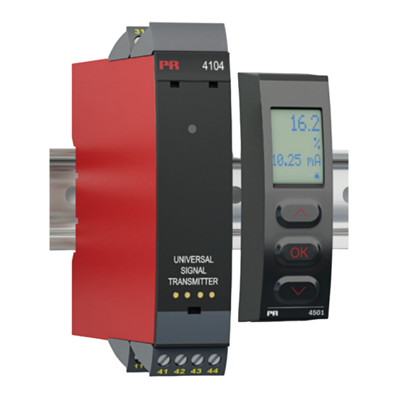
Page 10: Pr 4501 Display / Programming Front
Functions and configuration options are described in the section ”Configuration / operating the function keys”. mounting / installation • 4501 is a detachable display that can be mounted on the 4104 front for programming and signal monitoring. application • Communications interface for modification of operational parameters in 4104. -
Page 11: Connections
connEcTionS Input signals: Current 2-wire Tx 3-wire Tx Voltage (±) (±) Output signals: + V supply Current & voltage 2-wire 10 V 10 V (±) Supply: 21.6...253 VAC 19.2...300 VDC Safe Area or Zone 2 / Cl. 1, Div. 2, gr. A-D 41 0 4 V 1 0 0 - UK... -
Page 12: Order Codes
4104 = Universal signal transmitter 4501 = Display / programming front Specifications Environmental conditions: Specifications range ........-20°C to +60°C Storage temperature ........-20°C to +85°C Calibration temperature....... 20...28°C Relative humidity ......... < 95% RH (non-cond.) Protection degree ........IP20 Installation in pollution degree 2 & measurement / overvoltage category II. - Page 13 accuracy values Absolute Temperature Input accuracy coefficient ≤ ±0.05% of span ≤ ±0.01% of span / °C EMC immunity influence .......... < ±0.5% of span Extended EMC immunity: NAMUR NE 21, A criterion, burst ......... < ±1% of span of span = of selected range input specifications: current input: Signal range ..........
- Page 14 Passive 2-wire ma: Programmable ranges ......... 0-20 and 4-20 mA Direct or Inverted action V-curve function, 100-0-100% ....20-0-20 mA External 2-wire loop supply ....... 3.5 - 26 V common specifications current output: Signal range ..........0...23 mA (unipolar) / -23...+23 mA (bipolar) Current limit ..........
- Page 15 approvals: EMC 2004/108/EC ........EN 61326-1 LVD 2006/95/EC .......... EN 61010-1 UL, Standard for Safety ......UL 508 GOST R marine: Det Norske Veritas, Ships & Offshore ..Pending FM ............... 3025177 41 0 4 V 1 0 0 - UK...
-
Page 16: 4501 Display Readout Of Input 4-20 Ma Loop Error Detection And Signal "Outside Range
Error caused by No load on the current output Check measurement of analogue output - read * note AO.ER (only S4...20 mA) Communications test 4501 / 4104 NO.CO Connection error Hardware error - read ** note FL.ER Error in FLASH Configuration error - read ** note CO.ER... -
Page 17: Block Diagram
blocK DiagRam 3-wire Tx Voltage 2-wire Tx Current 41 0 4 V 1 0 0 - UK... -
Page 18: Configuration / Operating The Function Keys
Documentation for routing diagram. in general When configuring the 4104, you will be guided through all parameters and you can choose the settings which fit the application. For each menu there is a scrolling help text which is automatically shown in line 3 on the display. -
Page 19: Routing Diagram
RoUTing DiagRam If no key is activated for 1 minute, the display will return to the Power up default state 1.0 without saving configuration changes. 1 Increase value / choose next parameter 2 Decrease value / choose previous parameter 3 Accept the chosen value and proceed to the next menu Hold 3 Back to previous menu / return to menu 1.0 without saving -/+10 50.0... - Page 20 -/+20 -/+10 ZERO S4-20 99.99 VOLT 4-20 DOWN 60.0 PASS -19.99 CURR 0-20 NONE ACTI CURR 4-20 10.00 ACTI DISP.HI ANA.OUT O.RANGE OUT.ERR RESP OUT.MOD Txt 10 Txt 11 Txt 14 Txt 15 Txt 9 Txt 13 -/+10 -/+5 To default state 1.0 -/+1 2-10 0-10...
-
Page 21: Routing Diagram, Advanced Settings (Adv.set)
RoUTing DiagRam Advanced settings (ADV.SET) MEM, DISP, CAL, SIM PASS, LANG, SAVE OFUN LOAD SAVE SETUP MEMORY Txt 16 Txt 17 A.OUT DISP A.OUT TT0123 SETUP CONTRA LIGHT TAGNO_ LINE 3 Txt 18 Txt 19 Txt 20 Txt 21 10.00 10.00 8.00 SETUP... - Page 22 advanced functions The device gives access to a number of advanced functions which can be reached by answering “Yes” to the point “adv.set”. memory (mEm): In the memory menu you can SAVE the configuration of the device in the 4501, and then move the 4501 onto another device of the same type and LOAD the configuration in the new device.
-
Page 23: Scrolling Help Text In Display Line 3
ScRolling HElP TExT in DiSPlay linE 3 [01] Set correct password [16] Select Analog output function [02] Enter advanced setup menu? Enter Language setup [03] Select current input Enter Password setup Select voltage input Enter Simulation mode [04] Select 0..20 mA input range Perform Process calibration Select 4..20 mA input range Enter Display setup... - Page 24 Displays Programmable displays with a wide selection of inputs and outputs for display of temperature, volume and weight, etc. Feature linearisation, scaling, and difference measurement functions for programming via PReset software. Ex interfaces Interfaces for analogue and digital signals as well as HART signals between sensors / I/P converters / ®...
- Page 25 www.prelectronics.se sales@prelectronics.se www.prelectronics.co.uk sales@prelectronics.co.uk www.prelectronics.com sales@prelectronics.com www.prelectronics.cn sales@prelectronics.cn Head office Denmark www.prelectronics.com PR electronics A/S sales@prelectronics.dk Lerbakken 10 tel. +45 86 37 26 77 DK-8410 Rønde fax +45 86 37 30 85...
Need help?
Do you have a question about the 4104 and is the answer not in the manual?
Questions and answers