
Subscribe to Our Youtube Channel
Related Manuals for PR 4114


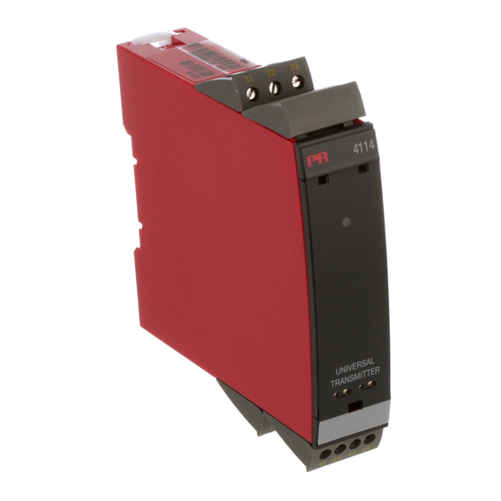
Summary of Contents for PR 4114
- Page 1 4 1 1 4 U n i v e r s a l t r a n s m i t t e r N o . 4 1 1 4 V 1 0 4 - U K F r o m s e r . n o . 1 2 1 5 2 4 0 0 1 S I G N A L S T H E B E S T...
- Page 2 PR electronics A/S tilbyder et bredt program af analoge og digitale signalbehandlingsmoduler til industriel automation. Programmet består af Isolatorer, Displays, Ex-barrierer, Temperaturtransmittere, Universaltransmittere mfl. Vi har modulerne, du kan stole på i selv barske miljøer med elektrisk støj, vibrationer og temperaturud- sving, og alle produkter opfylder de strengeste internationale stan- darder.
-
Page 3: Table Of Contents
When front LED lights red / display shows AO.ER .... Advanced features ............. Application ................. Technical characteristics ............ PR 4501 display / programming front ........ Applications ................ Order codes ............... 10 Electrical specifications ............10 Display readout on the 4501 of sensor error detection and input signal outside range ........ -
Page 4: Warning
SYSTEM 4000 must be mounted on a DIN rail according to DIN 46277. INSTAL LATION WARNING Do not open the front plate of the module as this will cause damage to the connector for the display / programming front PR 4501. This module contains no DIP-switches or jumpers. 4114V104-UK... -
Page 5: Symbol Identification
Should there be any doubt as to the correct handling of the device, please contact your local distributor or, alternatively, PR electronics A/S www.prelectronics.com 4114V104-UK... - Page 6 When disconnected, the device may be cleaned with a cloth moistened with distilled water. LIABILITY To the extent that the instructions in this manual are not strictly observed, the custom er cannot advance a demand against PR electronics A/S that would otherwise exist according to the concluded sales agreement. 4114V104-UK...
-
Page 7: Declaration Of Conformity
DECLARATION OF CONFORMITY As manufacturer PR electronics A/S Lerbakken 10 DK8410 Rønde hereby declares that the following product: Type: 4114 Name: Universal transmitter is in conformity with the following directives and standards: The EMC Directive 2004/108/EC and later amendments EN 613261 For specification of the acceptable EMC performance level, refer to the electrical specifications for the device. -
Page 8: How To Demount System 4000
When front LED lights red / display shows AO.ER PR 4114 is designed as a SIL 2 device with a high safety level. Therefore, a continuous measurement of the outgoing current is carried out on a 4...20 mA and 20...4 mA output signal. -
Page 9: Advanced Features
SIL 2 installations. Technical characteristics • When 4114 is used in combination with the 4501 display / programming front, all operational parameters can be modified to suit any application. As the 4114 is designed with electronic hardware switches, it is not necessary to open the device for setting of DIP-switches. • A green / red front LED indicates normal operation and malfunction. • Continuous check of vital stored data for safety reasons. -
Page 10: Pr 4501 Display / Programming Front
PR 4501 DISPLAY / PROGRAMMING FRONT Functionality The simple and easily understandable PReasy menu structure and the explanatory help texts guide you effortless ly and automatically through the configuration steps, thus making the product very easy to use. Functions and configuration options are described in the section ”Configuration / operating the function keys”. -
Page 11: Applications
APPLICATIONS Input signals: Volt Potentio- Current meter RTD and lin. R Connect., wires Order separately: 5910 CJC connector. Output signals: See the connection drawing on page 15. Analogue, 0/4...20 mA and voltage 10 V 10 V Supply: 21.6...253 VAC 19.2...300 VDC 4114V104-UK... -
Page 12: Order Codes
Order codes 4114 = Universal transmitter 4501 = Display / programming front 5910 = CJC connector Electrical specifications Specifications range ........-20°C to +60°C Common specifications: Supply voltage, universal ......21.6...253 VAC, 50...60 Hz or 19.2...300 VDC Max. consumption........≤ 2.0 W Fuse ............. - Page 13 Basic values Input Basic Temperature type accuracy coefficient ≤ ±4 µA ≤ ±0.4 µA / °C ≤ ±20 µV ≤ ±2 µV / °C Volt ≤ ±0.2°C ≤ ±0.01°C / °C Pt100 ≤ ±0.1 Ω ≤ ±0.01 Ω / °C Linear resistance ≤...
- Page 14 Cable resistance per wire (max.), RTD ..50 Ω Sensor current, RTD ........Nom. 0.2 mA Effect of sensor cable resistance (3- / 4-wire), RTD ......... < 0.002 Ω / Ω Sensor error detection, RTD ....... Yes Short circuit detection, RTD ......< 15 Ω TC input: Min.
-
Page 15: Display Readout On The 4501 Of Sensor Error Detection And Input Signal Outside Range
UL, Standard for Safety ......UL 508 of span = of the currently selected measurement range Display readout on the 4501 of sensor error detection and input signal outside range Sensor error check: Device: Configuration Sensor error detection: OUT.ERR=NONE. 4114 Else: 4114V104-UK... -
Page 16: Sensor Error Detection Limits
Error in FLASH 1) No load on the current out- Check measurement of analogue output current AO.ER put (only S4...20/S20...4 mA) Communications test 4501 / 4114 NO.CO Connection error Check that input signal matches input configuration IN.ER 1) Error levels on input Check that saved configuration in 4501 matches device TY.ER... -
Page 17: Connections
CONNECTIONS Supply: Inputs TC, internal RTD, 2-wire RTD, 3- / 4-wire Resistance, 2-wire CJC sensor 41 42 43 44 41 42 43 44 41 42 43 44 41 42 43 44 Resistance, Potentiometer 2-wire transmitter Current 3- / 4-wire 41 42 43 44 41 42 43 44 41 42 43 44 41 42 43 44... -
Page 18: Block Diagram
BLOCK DIAGRAM 2-wire transmitter Current Voltage Potentiometer Safety 4114V104-UK... -
Page 19: Configuration / Operating The Function Keys
Documentation for routing diagram. In general: When configuring the 4114, you will be guided through all parameters and you can choose the settings which fit the application. For each menu there is a scrolling help text which is automatically shown in line 3 on the display. - Page 20 Signal and sensor error indication without display front Status of the unit can also be read from the red/green LED in the front of the device. Green flashing LED 13 Hz indicates normal operation. Green flashing LED 1 Hz indicates sensor error. Steady green LED indicates internal error.
- Page 21 Please note, however, that when safety readback is enabled, a sensor error will be indicated as an error on the analogue output signal. In the CJC menu you can choose between external CJC connector and internal cold junction compensation. The external CJC connector (PR 5910) must be ordered separately. Memory...
-
Page 22: Routing Diagram
ROUTING DIAGRAM Power up If no key is activated for 1 minute, the display will return to the default state 1.0 without saving configuration changes. 1 Increase value / choose next parameter 2 Decrease value / choose previous parameter 3 Accept the chosen value and proceed to the next menu Hold 3 Back to previous menu / return to menu 1.0 without saving 50.0 12.0... - Page 23 S20-4 20-4 20-0 S4-20 23mA 4-20 999.9 VOLT 0/3.5mA 4172 4172 0-20 -199.9 CURR NONE -328 -328 100.0 CURR 4-20 23mA 150.0 DISP.HI ANA.OUT O.RANGE OUT.ERR OUT.LO OUT.HI Txt 14 Txt 36 Txt 37 Txt 38 Txt 41 Txt 42 10-2 10-0 1-0.2...
-
Page 24: Routing Diagram, Advanced Settings (Adv.set)
ROUTING DIAGRAM, ADVANCED SETTINGS (ADV.SET) 2.0 In the submenu simulation (SIM) you must DISP press 3 to return to the default state 1.0. PASS SAVE LANG LOAD SAVE SETUP MEMORY Txt 43 Txt 44 A.OUT DISP A.OUT SETUP CONTRA LIGHT VALVE 5 LINE 3 Txt 43... -
Page 25: Scrolling Help Text In Display Line 3
Enter display setup [13] Set display range low Perform memory operations [14] Set display range high [44] Load saved configuration into 4114 [16] Select Pt10 as sensor type Save 4114 configuration in 4501 Select Pt20 as sensor type [45] Adjust LCD contrast... - Page 26 Displays Programmable displays with a wide selection of inputs and outputs for display of temperature, volume and weight, etc. Feature linearisation, scaling, and difference measurement functions for programming via PReset software. Ex interfaces Interfaces for analogue and digital signals as well as HART signals between sensors / I/P converters / ®...
- Page 27 www.prelectronics.se sales@prelectronics.se www.prelectronics.co.uk sales@prelectronics.co.uk www.prelectronics.com sales@prelectronics.com www.prelectronics.cn sales@prelectronics.cn Head office Denmark www.prelectronics.com PR electronics A/S sales@prelectronics.dk Lerbakken 10 tel. +45 86 37 26 77 DK-8410 Rønde fax +45 86 37 30 85...
Need help?
Do you have a question about the 4114 and is the answer not in the manual?
Questions and answers