Winmate Full IP65 User Manual
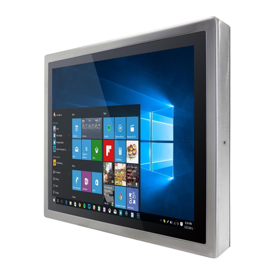
Stainless resistive panel pc
Hide thumbs
Also See for Full IP65:
- User manual (93 pages) ,
- Quick start manual (28 pages) ,
- User manual (89 pages)
Table of Contents
Advertisement
Quick Links
Download this manual
See also:
User Manual
Advertisement
Table of Contents

Related Manuals for Winmate Full IP65


Summary of Contents for Winmate Full IP65
- Page 1 Stainless Resistive Panel PC ® ® Intel Celeron Bay Trail-M N2930 1.83 GHz Full IP65 User Manual Version 1.0 Document Part Number: 9152111I101M...
-
Page 2: Copyright Notice
Warranty Winmate Inc. warranty guarantees that each of its products will be free from material and workmanship defects for a period of one year from the invoice date. If the customer... - Page 3 Customer Service We provide a service guide for any problem by the following steps: First, visit the website of our distributor to find the update information about the product. Second, contact with your distributor, sales representative, or our customer service center for technical support if you need additional assistance.
- Page 4 Advisory Conventions Four types of advisories are used throughout the user manual to provide helpful information or to alert you to the potential for hardware damage or personal injury. These are Notes, Important, Cautions, and Warnings. The following is an example of each type of advisory. NOTE: A note is used to emphasize helpful information IMPORTANT:...
-
Page 5: Safety Information
Safety Information WARNING! / AVERTISSEMENT! Always completely disconnect the power cord from your chassis whenever you work with the hardware. Do not make connections while the power is on. Sensitive electronic components can be damaged by sudden power surges. Only experienced electronics personnel should open the PC chassis. -
Page 6: Safety Precautions
Safety Precautions For your safety carefully read all the safety instructions before using the device. Keep this user manual for future reference. Always disconnect this equipment from any AC outlet before cleaning. Do not use liquid or spray detergents for cleaning. Use a damp cloth. ... - Page 7 CAUTION/ATTENTION Use the recommended mounting apparatus to avoid risk of injury. Utiliser l’appareil de fixation recommandé pour éliminer le risque de blessure. WARNING! / AVERTISSEMENT! Only use the connection cords that come with the product. When in doubt, please contact the manufacturer. Utiliser seulement les cordons d’alimentation fournis avec le produit.
-
Page 8: Important Information
Important Information Countries/ Area Symbol This equipment complies with essential requirements of: Electromagnetic Compatibility Directive(2014/30/EU) Low Voltage Directive (2014/35/EU) Restrictions of the use of certain hazardous European Union substances (RoHS) Directive (2011/65/EU) FCC Part 15 Subpart B Regulations Class B Federal Communications Commission Radio Frequency Interface Statement This device complies with part 15 FCC rules. - Page 9 European Union This equipment is in conformity with the requirement of the following EU legislations and harmonized standards. Product also complies with the Council directions. Electromagnetic Compatibility Directive (2014/30/EU) EN55024: 2010/ A1: 2015 o IEC61000-4-2: 2009 o IEC61000-4-3: 2006+A1: 2007+A2: 2010 o IEC61000-4-4: 2012 o IEC61000-4-5: 2014 o IEC61000-4-6: 2014...
-
Page 10: About This User Manual
About This User Manual This User Manual provides information about using the Winmate® IP65 Stainless Resistive Panel PC with Intel ® Celeron ® Bay Trail-M N2930 1.83 GHz processor. This User Manual applies to the IP65 Stainless Resistive Panel PC – R15IB3S-65C3, R17IB3S-65A1, R19IB3S-65M1, and W22IB3S-65A3. -
Page 11: Table Of Contents
Contents Preface ..........................ii About This User Manual ......................x Chapter 1: Introduction ......................2 1.1 Product Features ......................2 1.2 Package Content ......................3 1.3 Connector Placement ....................4 1.4 Physical Button and LED Indicators ................5 1.5 Schematics and Dimensions ..................6 1.5.1 Dimensions 15".................... - Page 12 6.3.1 VESA Mount ..................... 64 6.3.2 Yoke Mount ..................... 65 Chapter 7: Technical Support ....................67 7.1 Software Developer Support ..................67 7.1.1 Winmate Download Center ................67 7.1.2 Winmate File Share ..................67 7.2 Problem Report Form ....................68 Appendix A: Product Specifications ..................70 Appendix B: Ordering Information ..................73...
- Page 13 Introduction This chapter gives you product overview, describes features and hardware specification. You will find all accessories that come with the device in the packing list. Mechanical dimensions and drawings included in this chapter. IP65 Stainless Resistive Touch Panel PC...
-
Page 14: Chapter 1: Introduction
All of the models in the series are sealed to IP65 standard. Stainless housing features anti-corrosion properties making it suitable for food, chemical and pharmaceutical industries. Winmate® IP65 Stainless Resistive Panel PC goes beyond that of the standard industrial panel computers with rugged construction, powerful performance, and flexible mounting options. -
Page 15: Package Content
User Manual Chapter 1 Introduction 1.2 Package Content Carefully remove the box and unpack your Panel PC. Please check if all the items listed below are inside your package. If any of these items are missing or damaged contact us immediately. -
Page 16: Connector Placement
User Manual Chapter 1 Introduction 1.3 Connector Placement IP65 Flat Stainless Resistive Panel PC has IP65 type connectors with protection cap. For cable specifications refer to the Ch.2,“Cable Specifications” of this user manual. IP65 Stainless Resistive Panel PC... -
Page 17: Physical Button And Led Indicators
User Manual Chapter 1 Introduction 1.4 Physical Button and LED Indicators Physical Button and LED Indicators located on the rear side of the Panel PC. Physical Buttons Icon Button Description Reset Press to reset the system Power On/ Press to power on or power off the device LED Indicators LED Type Status... -
Page 18: Schematics And Dimensions
User Manual Chapter 1 Introduction 1.5 Schematics and Dimensions This section contains mechanical drawing of the panel PC. Notice that this is a simplified drawing and some components are not marked in detail. 1.5.1 Dimensions 15" Unit: mm 1.5.2 Dimensions 17" Unit: mm IP65 Stainless Resistive Panel PC... -
Page 19: Dimensions 19
User Manual Chapter 1 Introduction 1.5.3 Dimensions 19” Unit: mm 1.5.4 Dimensions 21.5” Unit: mm IP65 Stainless Resistive Touch Panel PC... -
Page 20: Getting Started
Getting Started This chapter tells you important information on power supply, adapter and precautions tips. Pay attention to power considerations. IP65 Stainless Resistive Panel PC... -
Page 21: Chapter 2: Getting Started
User Manual Chapter 2 Getting Started Chapter 2: Getting Started This chapter provides information on how to connect the panel PC to the source of power, connector pinouts and the guideline to turn on/off the Panel PC. 2.1 Powering On 2.1.1 AC Adapter Components AC Adapter supplied with the power cord. -
Page 22: Power Considerations
User Manual Chapter 2 Getting Started ALTERNATING CURRENT / MISE À LE TERRE! This product must be grounded. Use only a grounded AC outlet. Install the additional PE ground wire if the local installation regulations require it. *If you do not use a grounded outlet while using the device, you may notice an electrical tingling sensation when the palms of your hands touch the device. -
Page 23: Connecting The Power
User Manual Chapter 2 Getting Started 2.1.4 Connecting the Power Cable Mounting Instruction Connect the AC adapter to the DC-in jack connector located on the back side of the Panel PC. Connect the power cord to AC adapter. Plug the power cord to the AC outlet and the device will turn on automatically. Note: Power cords vary in appearance by region and country. -
Page 24: Connector Pin Assignments
User Manual Chapter 2 Getting Started 2.2 Connector Pin Assignments This Panel PC is equipped with four connectors which are IP65 level and fool-proofing design. Use only the cables that are included in the package. The pin assignments of the cables are as follows. -
Page 25: Serial Cable
User Manual Chapter 2 Getting Started 2.2.2 Serial Cable The IP65 Stainless Resistive Panel PC has IP65 serial port connector. Use serial cable to connect serial interfaces. IP65 Stainless Resistive Panel PC... -
Page 26: Ethernet Cable
User Manual Chapter 2 Getting Started 2.2.3 Ethernet Cable The IP65 Stainless Resistive Panel PC has IP65 Ethernet connector. Use Ethernet cable to connect the Panel PC to the Internet. IP65 Stainless Resistive Panel PC... -
Page 27: Usb 2.0 Cable
Chapter 2 Getting Started 2.2.4 USB 2.0 Cable Flat IP65 Stainless Resistive Panel PC has one Full IP65 USB2.0 connector. Use USB2.0 cable to connect external devices such as mouse or keyboard to the Panel PC. IP65 Stainless Resistive Panel PC... -
Page 28: Turning On And Off
User Manual Chapter 2 Getting Started 2.3 Turning On and Off The unit is configured to Power ON when is connected to the power source (refer to Ch.2, “Powering On” section of this user manual for more details on how to power on the HMI device). - Page 29 Operating the Device This chapter provides detailed information on how to operate the device. If you have been using touch-screen Panel PCs before, the interface may look familiar. Sections include system settings parameters. IP65 Stainless Resistive Panel PC...
-
Page 30: Chapter 3: Operating The Device
User Manual Chapter 3 Operating the Device Chapter 3: Operating the Device In this chapter you will find instructions on how to operate the Panel PC with Hot Tab. 3.1 Operating System IP65 Stainless Resistive Touch Panel PC supports several versions of Windows OS: Windows 10 IoT Enterprise, Windows Embedded 8.1 Industry Pro, Windows Embedded 8 Standard, Windows 7 Pro for Embedded Systems, and Windows Embedded Standard 7 –... -
Page 31: How To Enable Watchdog
Operating the Device 3.2 How to Enable Watchdog To enable Watchdog, you need to download Winmate Watchdog utility. Find more information on Watchdog in “Watchdog Guide” that you can download from Winmate Download Center or File Share. Refer to the Ch.7, “Technical Support”... - Page 32 AMI UEFI BIOS Setup BIOS Setup Utility is a program for configuration basic Input / Output system settings of the computer for optimum use. This chapter provides information on how to use BIOS setup, its functions and menu. IP65 Stainless Resistive Panel PC...
-
Page 33: Chapter 4: Ami Uefi Bios Setup
User Manual Chapter 4 AMI UEFI BIOS Setup Chapter 4: AMI UEFI BIOS Setup BIOS Setup Utility is a program for configuration basic Input / Output system settings of the computer for optimum use. This chapter provides information on how to use BIOS setup, its functions and menu. - Page 34 User Manual Chapter 4 AMI UEFI BIOS Setup The following Keys can be used after entering the BIOS Setup. Function General Help Previous Values Optimized Defaults Save & Exit Exit Change Opt. Enter Select or execute command Cursor ↑ Moves to the previous item Cursor ↓...
-
Page 35: Main Menu
User Manual Chapter 4 AMI UEFI BIOS Setup 4.2.1 Main Menu When you enter BIOS setup, the first menu that appears on the screen is the main menu.It contains the system information including BIOS version, processor RC version, system language, time, and date. Immediately after the [DEL] key is pressed during startup, the main BIOS setup menu appears: BIOS Setting... -
Page 36: Advanced Menu
User Manual Chapter 4 AMI UEFI BIOS Setup 4.2.2 Advanced Menu The advanced menu also uses to set configuration of the CPU and other system devices. There are sub menus on the left frame of the screen. IMPORTANT: Handle advanced BIOS settings page with caution. Any changes can affect the operation of your computer. - Page 37 User Manual Chapter 4 AMI UEFI BIOS Setup PPM Configuration Configures PPM Enter Opens submenu settings Thermal Configures Thermal Enter Opens submenu Configuration Parameters IDE Configuration Configures IDE Enter Opens submenu Parameters Miscellaneous Configures Enter Opens submenu Configuration Miscellaneous Parameters CSM Configuration Configures CSM Enter...
- Page 38 User Manual Chapter 4 AMI UEFI BIOS Setup 4.2.2.1 ACPI Settings Advanced Configuration and Power Interface (ACPI) settings allow to control how the power switch operates. The power supply can be adjusted for power requirements. You can use the screen to select options of ACPI configuration. A description of the selected items will appear on the right side of the screen.
- Page 39 User Manual Chapter 4 AMI UEFI BIOS Setup 4.2.2.2 F81866 Super IO Configuration You can use the screen to select options for Super IO Configuration, and change the value of the option selected. A description of the selected item appears on the right side of the screen.
- Page 40 User Manual Chapter 4 AMI UEFI BIOS Setup GPI0 Port Configuration You can use the screen to change GPI0 Port setting. Use these items to set parameters related to PIN3-PIN14 Control. 4.2.2.3 Hardware Monitor You can check PC Health Status parameters such as system temperature, fan speed etc. IP65 Stainless Resistive Panel PC...
- Page 41 User Manual Chapter 4 AMI UEFI BIOS Setup 4.2.2.4 S5 RTC Wake Settings Wake system from S5 enables or disables system wake on alarm event. It allows you to wake up the system in a certain time. Wake System from S5 with fixed time setting Select Fixed Time to set the system to wake on the specified time.
- Page 42 User Manual Chapter 4 AMI UEFI BIOS Setup Wake system from S5 after dynamic time setting Select Dynamic Time to set the system to wake on the current time + increase minute (s). IP65 Stainless Resistive Panel PC...
- Page 43 User Manual Chapter 4 AMI UEFI BIOS Setup 4.2.2.5 CPU Configuration BIOS Setting Description Setting Option Effect Socket CPU This item contains Enter Open sub-menu Information socket specific CPU information. CPU Thermal Thermal control Enter Open sub-menu Configuration Limit CPUID Limits CPIID Disabled/Enabled Enable/Disable this...
- Page 44 User Manual Chapter 4 AMI UEFI BIOS Setup 4.2.2.6 PPM Configuration BIOS Setting Description Setting Option Effect CPU C State Report Shows CPU C State Enabled/ Enable or Disable Report Disabled CPU C state report to OS Max CPU C-State Allows to enter C1, C3, C6, C7, Enable or Disable...
- Page 45 User Manual Chapter 4 AMI UEFI BIOS Setup 4.2.2.7 Thermal Configuration This menu allows controlling thermal settings of the computer. Refer to the descriptions on the top right side of the screen for detailed information about each setting. BIOS Setting Description Setting Option Effect...
- Page 46 User Manual Chapter 4 AMI UEFI BIOS Setup 4.2.2.8 IDE Configuration BIOS Setting Description Setting Option Effect Serial- ATA (SATA) Responsible for Enabled/ Enable or disable supporting chipset Disabled this function drives with SATA interface. SATA Speed Allows forcing the Gen1 The maximum Support...
- Page 48 User Manual Chapter 4 AMI UEFI BIOS Setup SATA Mode This option specifies the [AHCI] Selecting this option allows operation mode of you to take full advantage of modern IDE / SATA- the extended host controller controller chipset SATA II [IDE] SATA controller will operate in a mechanism similar to a...
- Page 49 User Manual Chapter 4 AMI UEFI BIOS Setup 4.2.2.9 Miscellaneous Configuration OS Selection This item allows users to select the proper Operating System. BIOS Setting Description Setting Option Effect Windows 8.X Allows user to Enter Use Windows 8.X choose the proper Windows 7 Allows user to Enter...
- Page 50 User Manual Chapter 4 AMI UEFI BIOS Setup 4.2.2.10 CSM Configuration BIOS Setting Description Setting Effect Option CSM Support The Compatibility Support Enabled/ Enable or disable Module (CSM) is a Disabled the Compatibility component of the UEFI Support Module firmware that provides legacy BIOS compatibility by emulating a BIOS environment, allowing legacy...
- Page 52 User Manual Chapter 4 AMI UEFI BIOS Setup Video Specifies which Video option ROM UEFI Only UEFI option is booted ROMs are booted Legacy Only Legacy option ROMs are booted Other PCI Specifies which option ROM is UEFI Only UEFI option Devices booted for devices other than the ROMs are booted...
- Page 54 User Manual Chapter 4 AMI UEFI BIOS Setup XHCI Hand‐off This is a Disable Disables this workaround for OSs function without XHCI hand‐ Enable Enables this off support. function EHCI Hand‐off This is a Disable Disables this workaround for OSs function without ECHI hand‐...
- Page 55 User Manual Chapter 4 AMI UEFI BIOS Setup 4.2.2.12 Platform Trust Technology BIOS Setting Description Setting Option Effect fTPM Trusted Platform Enabled/Disabled Enables or disables Module parameters this function IP65 Stainless Resistive Touch Panel PC...
- Page 56 User Manual Chapter 4 AMI UEFI BIOS Setup 4.2.2.13 Security Configuration BIOS Setting Description Setting Option Effect Trusted Execution Enabled/Disabled Enables or disables Technology this function parameters TXE HMRFPO TXE HMRFPO Enabled/Disabled Enables or disables parameters this function TXE Firmware TXE Firmware Enabled/Disabled Enables or disables...
-
Page 57: Chipset Menu
User Manual Chapter 4 AMI UEFI BIOS Setup 4.2.3 Chipset Menu For items marked with ►, please press <Enter> for more options. BIOS Setting Description Setting Option Effect High Precious Allow to set up Enabled/ Enables/Disables Timer High Precious Disabled this function Timer settings Restore AC Power... -
Page 58: Security Menu
User Manual Chapter 4 AMI UEFI BIOS Setup 4.2.4 Security Menu In the Security menu, users can set administrator password, user password, and HDD security configuration. BIOS Setting Description Setting Option Effect Administrator Displays whether Enter Enter password Password or not an administrator password has been set. -
Page 59: Boot Configuration
User Manual Chapter 4 AMI UEFI BIOS Setup 4.2.5 Boot Configuration The Boot menu sets the sequence of the devices to be searched for the operating system. The bootable devices will be automatically detected during POST and shown here, allowing you to set the sequence that the BIOS uses to look for a boot device from which to load the operating system. - Page 60 User Manual Chapter 4 AMI UEFI BIOS Setup Fast Boot Enables or disables Disabled Disables this Fast Boot to function shorten the OS Enabled Enables this boot process. function (Default: Disabled). Boot Mode Select Specifies which Legacy Only Legacy option mode will be used is booted for booting...
-
Page 61: Save & Exit
User Manual Chapter 4 AMI UEFI BIOS Setup 4.2.6 Save & Exit The Exit menu displays a way how to exit BIOS Setup utility. After finishing your settings, you must save and exit for changes to be applied. BIOS Setting Description Setting Option Effect... - Page 62 User Manual Chapter 4 Driver Installation Discard Changes Reset system setup Enter <YES> Saves the changes and Reset without saving any changes Enter <NO> Return to the BIOS Setup Main Menu Save Changes Save changes done Enter <YES> Saves the changes so far to any of the setup options.
-
Page 63: Using Recovery Wizard To Restore Computer
User Manual Chapter 4 Driver Installation 4.3 Using Recovery Wizard to Restore Computer Note: Before starting the recovery process, make sure to backup all user data. The data will be lost after the recovery process. To enable quick one-key recovery procedure: ... - Page 64 User Manual Chapter 4 Driver Installation Wait the recovery process to complete. During the recovery process, a command prompt will show up to indicate the percent of recovery process complete. The system will restart automatically after recovery completed. IP65 Stainless Resistive Panel PC...
-
Page 65: Driver Installation
Driver Installation This chapter describes how to install all necessary drivers. IP65 Stainless Resistive Touch Panel PC... -
Page 66: Chapter 5: Driver Installation
User Manual Chapter 5 Driver Installation Chapter 5: Driver Installation This chapter provides guideline to driver installations. 5.1 Chipset Driver Step 1 Insert the CD that comes with the motherboard. Open the file document “Chipset Driver” and click “infinst_auto.exe” to install driver. Step 2 Click Next to continue. - Page 67 User Manual Chapter 5 Driver Installation Step 3 Click Yes to agree the license terms. Step 4 Click Next to install the driver. Step 5 Software setup progress window will appear, click Next to continue. Step 6 Click “Yes, I want to restart this computer now” to finish the installation. IP65 Stainless Resistive Touch Panel PC...
-
Page 68: Graphics Driver
User Manual Chapter 5 Driver Installation 5.2 Graphics Driver Step 1 Insert the CD that comes with the motherboard. Open the file document “Graphics Driver” and click Setup to execute the setup. Step 2 Setup Welcome Window will appear, click Next to continue the process. Step 3 Carefully read the license terms and click Yes to agree. -
Page 69: Intel Sideband Fabric Device (Intel Mbi) Driver (Windows 8)
User Manual Chapter 5 Driver Installation 5.3 Intel Sideband Fabric Device (Intel MBI) Driver (Windows 8) Step 1 Insert the CD that comes with the motherboard. Open the file document “MBI” and click “Setup.exe” to install the driver. Step 2 Welcome to the setup program window will appear, click Next to start the installation. -
Page 70: Intel Trusted Engine Interface (Intel Txe) Driver
User Manual Chapter 5 Driver Installation 5.4 Intel Trusted Engine Interface (Intel TXE) Driver Step 1 Insert the CD that comes with the motherboard. Open the file document “TXE” and click “Setup TXE.exe” to install the driver. Step 2 Welcome to the setup program window will appear, click Next to start the installation. -
Page 71: Intel Network Connections Driver
User Manual Chapter 5 Driver Installation 5.5 Intel Network Connections Driver User must confirm the type of operating system is being used before installing Intel Network Connections. Follow the steps below to complete the installation. Step 1 Click “PROWin64.exe” Step 2 Click Yes to start the installation. Step 3 Welcome window will appear, click Next to install the driver. -
Page 72: Audio Driver
User Manual Chapter 5 Driver Installation 5.6 Audio Driver The ALC886 series are high-performance 7.1+2 channel high definition audio codecs that provide ten DAC channels for simultaneous support of 7.1 sound playback, plus 2 channels of independent stereo sound output (multiple streaming) through the front panel stereo outputs. - Page 73 Mounting Solutions This chapter provides step-by-step mounting guide for all available mounting options. IP65 Stainless Resistive Touch Panel PC...
-
Page 74: Chapter 6: Mounting Solutions
User Manual Chapter 6 Mounting Solutions Chapter 6: Mounting Solutions This chapter provides mounting guide for all available mounting options. Pay attention to cautions and warning to avoid any damages. WARNING! / AVERTISSEMENT! Follow mounting instructions and use recommended mounting hardware to avoid the risk of injury. -
Page 75: Safety Precautions
User Manual Chapter 6 Mounting Solutions 6.2 Safety Precautions Observe the following common safety precautions before installing any electronic device: • Use separate, non-intersecting paths to route power and networking wires. If power wiring and device wiring paths must be crossed make sure the wires are perpendicular at the intersection point. -
Page 76: Mounting Guide
Refer to sub-sections below for more details. 6.3.1 VESA Mount The IP65 Stainless Resistive Touch Panel PC has VESA mount holes on the rear side. Follow instructions below to mount the unit with VESA Mount bracket (not supplied by Winmate). Size VESA Plate... -
Page 77: Yoke Mount
6.3.2 Yoke Mount Yoke Mount solution allows installing the Panel PC with the bracket (not supplied by Winmate). Mounting instruction: 1. Place the Panel PC on the bracket stand, aiming screw holes for each other. 2. Secure screws to fix the device upon the bracket stand. -
Page 78: Technical Support
Technical Support This chapter includes directory to Winmate technical support. IP65 Stainless Resistive Touch Panel PC... -
Page 79: Chapter 7: Technical Support
This chapter includes technical support documents and software developing kit (SDK). If any problem occurs fill in problem report form enclosed and immediately contact us. 7.1 Software Developer Support Winmate provides the following SDK and Utilities for IP65 Stainless Resistive Touch Panel Item File Type Description Watchdog SDK... -
Page 80: Problem Report Form
User Manual Chapter 7 Technical Support 7.2 Problem Report Form IP65 Stainless Resistive Touch Panel PC Customer name: Company: Tel.: Fax: E-mail: Date: Product Serial Number: _____________________________________________________ Problem Description: Please describe the problem as clearly as possible. Detailed description of the occurred problem will allow us to find the best solution to solve the problem as soon as possible. -
Page 81: Product Specifications
Product Specifications This section includes product specifications. Appendix IP65 Stainless Resistive Touch Panel PC... -
Page 82: Appendix A: Product Specifications
User Manual Appendix A Product Specifications Appendix A: Product Specifications Hardware Specifications Model Name R15IB3S-65C3 R17IB3S-65A1 R19IB3S-65M1 W22IB3S-65A3 Display 15” Size 17” 19” 21.5” Resolution 1024 x 768 1280 x 1024 1280 x 1024 1920 x 1080 Brightness (typ.) (typ.) (typ.) (typ.) 700 : 1... - Page 83 Yoke Mount, VESA Mount Environmental Consideration Operating 0°C to +45°C Temperature Operating 30% to 90% (non-condensing) Humidity IP Rating Full IP65 Power Specifications Power Input 12V DC IN (Lockable Power Jack) Power 38W (typ.) 43W (typ.) 45W (typ.) 56W (typ.)
- Page 84 Ordering Information This section includes product specifications. Appendix IP65 Stainless Resistive Touch Panel PC...
-
Page 85: Appendix B: Ordering Information
User Manual Appendix B Ordering Information Appendix B: Ordering Information IP65 Stainless Resistive Touch Panel PC available for ordering in the following configurations. Panel PC SODIMM DDR3L Max 8GB Windows 10 IoT Enterprise Windows Embedded 8.1 Industry Pro Windows Embedded 8 Standard Windows Embedded 7 Standard Storage 2.5”... - Page 86 Winmate Inc. 9F, No.111-6, Shing-De Rd., San-Chung District, New Taipei City 24158, Taiwan, R.O.C Tel: 886-2-8511-0288 Fax: 886-2-8511-0211 Email: sales@winmate.com.tw Official website: www.winmate.com...
Need help?
Do you have a question about the Full IP65 and is the answer not in the manual?
Questions and answers