Moxa Technologies SDS-3008 Series Quick Installation Manual
Industrial smart ethernet switch
Hide thumbs
Also See for SDS-3008 Series:
- User manual (51 pages) ,
- Quick installation manual (23 pages)
Table of Contents
Advertisement
Quick Links
Download this manual
See also:
User Manual
Quick Installation Guide
Moxa's Industrial Smart Ethernet Switch
Moxa Americas:
Toll-free: 1-888-669-2872
Tel:
1-714-528-6777
Fax:
1-714-528-6778
Moxa Europe:
Tel:
+49-89-3 70 03 99-0
Fax:
+49-89-3 70 03 99-99
Moxa India:
Tel:
+91-80-4172-9088
Fax:
+91-80-4132-1045
SDS-3008 Series
Edition 2.0, March 2017
Technical Support Contact Information
www.moxa.com/support
2017 Moxa Inc. All rights reserved.
Moxa China (Shanghai office):
Toll-free: 800-820-5036
Tel:
+86-21-5258-9955
Fax:
+86-21-5258-5505
Moxa Asia-Pacific:
Tel:
+886-2-8919-1230
Fax:
+886-2-8919-1231
P/N: 1802300800011
*1802300800011*
Advertisement
Table of Contents

Related Manuals for Moxa Technologies SDS-3008 Series


Summary of Contents for Moxa Technologies SDS-3008 Series
-
Page 1: Quick Installation Guide
SDS-3008 Series Quick Installation Guide Moxa’s Industrial Smart Ethernet Switch Edition 2.0, March 2017 Technical Support Contact Information www.moxa.com/support Moxa Americas: Moxa China (Shanghai office): Toll-free: 1-888-669-2872 Toll-free: 800-820-5036 Tel: 1-714-528-6777 Tel: +86-21-5258-9955 Fax: 1-714-528-6778 Fax: +86-21-5258-5505 Moxa Europe: Moxa Asia-Pacific:... -
Page 2: Package Checklist
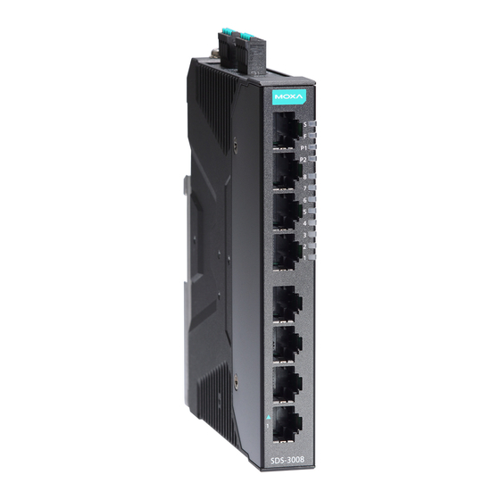
Overview The SDS-3008 industrial smart Ethernet switch is the ideal device for IA engineers and automation machine builders to make their networks compatible with the vision of Industry 4.0. By breathing life into machines and control cabinets, the smart switch simplifies daily tasks with its easy configuration and easy installation. - Page 3 SDS-3008 Panel Layout 1. 1 to 8 10/100BaseT(X) ports (bottom to top) 2. System status LEDs (top to bottom) STATE LED indicator (Green), FAULT LED indicator (Red), PWR1 LED indicator (Amber), PWR2 LED indicator (Amber) 3. 1 to 8 port status LEDs (bottom to top) •...
-
Page 4: Din-Rail Mounting
Mounting Dimensions; unit = mm (inches) DIN-Rail Mounting There are 2 options for DIN-rail mounting that can be adopted on a SDS-3008. Option 1 is the default type when shipped. Option 1 (Default): When shipped, the metal DIN-rail mounting kit is fixed to the back panel of the SDS-3008. - Page 5 Suggested Removal Method STEP 1—Pull down the latch on the DIN-rail kit with a screwdriver. STEPS 2 & 3—Slightly pull the SDS-3008 forward and lift up to remove it from the mounting rail. Option 2 (when side cabling is needed): The metal DIN-rail mounting kit can be fixed to the side panel (mold side) of the SDS-3008 (horizontal or vertical).
-
Page 6: Wiring Requirements
STEP 2—Insert the upper lip of the DIN-rail kit into the mounting rail. STEP 3—Press the SDS-3008 towards the mounting rail until it snaps into place. Suggested Removal Method STEP 1—Pull down the latch on the DIN-rail kit with a screwdriver. STEPS 2 &... - Page 7 Be sure to read and follow these important guidelines: • Use separate paths to route wiring for power and devices. If power wiring and device wiring paths must cross, make sure the wires are perpendicular at the intersection point. NOTE Do not run signal or communications wiring and power wiring through the same wire conduit.
-
Page 8: Wiring The Relay Contact
In order to tighten the wire properly, ① use a small flathead NOTE We suggest the length of the pin type cable terminal is 8 mm. the terminal block connector before and during ② inserting the screwdriver to press the push-in button beside each terminal of wire. - Page 9 NOTE The relay output of the SDS-3008 reflects a potential-free, normally opened solid-state relay. Therefore, not only when user-configured events are triggered but also when there is no power supply to the switch it will open. To indicate a fault has occurred one can integrate the relay contact on the smart switch with an external alarming system circuit so that the status of user-configured events or no power supply can be monitored.
-
Page 10: Wiring The Redundant Power Inputs
Wiring the Redundant Power Inputs (12/24/48 VDC) The SDS-3008 has two sets of power inputs–power input 1 (PWR 1/P1) and power input 2 (PWR 2/P2). The top view of the terminal block connector and the positions of the power inputs are shown below. Take the following steps to wire the redundant power inputs: STEP 1: Insert the Positive/Negative DC wires into the V1+/V1- terminal for PWR 1 and/or V2+/V2- terminal for PWR 2. -
Page 11: 10/100Baset(X) Ethernet Port Connection
NOTE ABC-02-USB Installation Plug the ABC-02-USB into the USB storage port of the SDS-3008. We suggest securing the ABC-02-USB on the wall with an M4 screw. 10/100BaseT(X) Ethernet Port Connection The 10/100BaseT(X) ports located on the front panel of the SDS-3008 are used to connect to Ethernet-enabled devices. -
Page 12: Reset Button
Reset Button The reset button can perform two functions. One is to reset the industrial smart Ethernet switch back to factory default settings and the other is to perform a quick back up of configuration and log files to the ABC-02-USB automatic backup configurator. -
Page 13: Specifications
Color Status Description FAULT Solid light 1. System is in the event of failure, or is under quick inspection 2. Invalid port connection Blinking 1. RAM test fail / switch initialization fail 2. Firmware checksum fail / Uncompressed fail Light off The system is operating normally STATE STATE: Green... -
Page 14: Environmental Limits
Switch Properties Max. Number of VLANs VLAN ID Range VID 1 to 4094 MAC Table Size Packet Buffer Size 3 Mbit Interface RJ45 Ports 10/100BaseT(X) auto negotiation speed Storage Port USB storage (Type A connector for ABC-02-USB) Alarm Contact (Relay 1 normally open solid-state relay output with Output) current carrying capacity of 1 A @ 24 VDC... - Page 15 Standards and Certifications Safety UL 61010-2-201, EN 60950-1 (Preliminary) EN 61000-6-2/6-4 CISPR 22, FCC Part 15B Class A IEC 61000-4-2 ESD: Contact: 6 kV; Air: 8 kV IEC 61000-4-3 RS: 80 MHz to 1 GHz: 20 V/m IEC 61000-4-4 EFT: Power: 2 kV; Signal: 2 kV IEC 61000-4-5 Surge: Power: 2 kV;...
Need help?
Do you have a question about the SDS-3008 Series and is the answer not in the manual?
Questions and answers