Table of Contents
Advertisement
Quick Links
Quick Installation Guide
Moxa Americas:
Toll-free: 1-888-669-2872
Tel:
1-714-528-6777
Fax:
1-714-528-6778
Moxa Europe:
Tel:
+49-89-3 70 03 99-0
Fax:
+49-89-3 70 03 99-99
Moxa India:
Tel:
+91-80-4172-9088
Fax:
+91-80-4132-1045
TN-5916 Series
Moxa ToughNet NAT Router
Edition 2.0, February 2017
Technical Support Contact Information
www.moxa.com/support
2017 Moxa Inc. All rights reserved.
Moxa China (Shanghai office):
Toll-free: 800-820-5036
Tel:
+86-21-5258-9955
Fax:
+86-21-5258-5505
Moxa Asia-Pacific:
Tel:
+886-2-8919-1230
Fax:
+886-2-8919-1231
P/N: 1802059160011
*1802059160011*
Advertisement
Table of Contents

Subscribe to Our Youtube Channel
Related Manuals for Moxa Technologies TN-5916 Series


Summary of Contents for Moxa Technologies TN-5916 Series
- Page 1 TN-5916 Series Quick Installation Guide Moxa ToughNet NAT Router Edition 2.0, February 2017 Technical Support Contact Information www.moxa.com/support Moxa Americas: Moxa China (Shanghai office): Toll-free: 1-888-669-2872 Toll-free: 800-820-5036 Tel: 1-714-528-6777 Tel: +86-21-5258-9955 Fax: 1-714-528-6778 Fax: +86-21-5258-5505 Moxa Europe: Moxa Asia-Pacific:...
-
Page 2: Package Checklist
M12 ports with 4 bypass relay ports. Furthermore, with a -40 to 75°C operating temperature and IP54-rated waterproof enclosure, the router can be deployed in harsh environments. The TN-5916 series Ethernet routers are compliant with EN 50155/50121-4 requirements, making the router suitable for a variety of industrial applications. -
Page 3: Recommended Optional Accessories
Recommended Optional Accessories • CBL-M23(FF6P)Open-BK-100-IP67: 1-meter M23 to 6-pin power cable with IP67-rated female 6-pin M23 connector • CBL-M12D(MM4P)/RJ45-100 IP67: 1-meter M12-to-RJ45 Cat-5E UTP Ethernet cable with IP67-rated male 4-pin M12 D-coded connector • CBL-M12(FF5P)/OPEN-100 IP67: 1-meter M12-to-5-pin power cable with IP67-rated female 5-pin M12 A-coded connector •... -
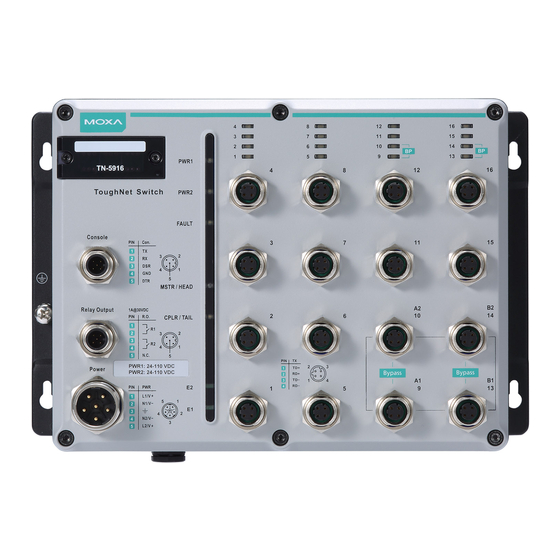
Page 4: Tn-5916 Panel Layouts
15. Waterproof vent 16. Product label 17. 12 screw holes for DIN-rail mounting kit 18. E2 LED: Not used by the TN-5916 series 19. E1 LED: Not used by the TN-5916 series 20. Ports 9-10, 13-14 with relay bypass function... -
Page 5: Mounting Dimensions (Unit = Mm)
DO NOT open or remove the vent (#15). Removing the seal will invalidate the warranty. Ports (including 3, 5, and 14) that are not in use must be tightly covered with protective caps (an optional accessory) to ensure IP54/IP67-rated protection. Mounting Dimensions (unit = mm) TN-5916 Series - 5 -... -
Page 6: Panel/Wall Mounting
Panel/Wall Mounting STEP 1: Mounting the TN-5916 to a wall requires 4 screws. Use the ToughNet router as a guide to mark the correct positions of the 4 screws. STEP 2: Use the 4 screws in the panel mounting kit. If you would like to use your own screws, make sure the screw head is between 6.0 mm and 7.0 mm in diameter and... -
Page 7: Wiring Requirements
STEP 2: If the spring-loaded bracket is locked in place, push the recessed button to release it. Once released, you should feel some resistance from the spring as you slide the bracket up and down a few millimeters in each direction. -
Page 8: Grounding The Toughnet Nat Router
ATTENTION Safety First! Be sure to disconnect the power cord before installing and/or wiring your Moxa router. This device has UL 508 approval. Use copper conductors only, 60 to 75°C, and tighten to 4.5 inch-pounds. For use in pollution degree 2 environments. ATTENTION Safety First! Observe all electrical codes dictating the maximum current... -
Page 9: Connecting The Power Supplies
Connecting the Power Supplies The ToughNet TN-5916 series routers support two sets of power supplies—power input 1 and power input 2. The M23 6-pin male connector on the TN-5916’s front panel is used for the dual power inputs. -
Page 10: Connecting The Relay Outputs
Connecting the Relay Outputs Each TN-5916 router has two sets of relay outputs—relay output 1 and relay output 2.The M12 A-coded 5-pin male connector on the TN-5916 front panel is used for the two relay outputs. Use a power cord with an M12 A-coded 5-pin female connector to connect the relay contacts. - Page 11 M12 (4-pin, M) to M12 (4-pin, M) Cross-Over Cable Wiring M12 (4-pin, M) to M12 (4-pin, M) Straight-Through Cable Wiring M12 (4-pin, M) to RJ45 (8-pin) Cross-Over Cable Wiring M12 (4-pin, M) to RJ45 (8-pin) Straight-Through Cable Wiring - 11 -...
-
Page 12: Bypass Relay Function
Bypass Relay Function The TN-5916 is equipped with a bypass relay function. When the router is operating normally, these bypass ports work in the same way as the other ports. That is, frame ingressions are processed and then forwarded. If the router stops working due to a power failure, the bypass relay function will be triggered to ensure non-stop data communication. -
Page 13: Led Indicators
LED Indicators Several LED indicators are located on the ToughNet router’s front panel. The function of each LED is described in the table below. Color State Description System LEDs Power is being supplied to power input PWR1. PWR1 AMBER Power is not being supplied to power input PWR1 Power is being supplied to power input PWR2. -
Page 14: Specifications
Specifications Technology Standards IEEE 802.3 for 10BaseT IEEE 802.3u for 100BaseT(X) IEEE 802.3x for Flow Control IEEE 802.1D for Spanning Tree Protocol IEEE 802.1w for Rapid STP IEEE 802.1Q for VLAN Tagging IEEE 802.1p for Class of Service IEEE 802.3ad for static Port Trunk Protocols IGMPv1/v2, SNMPv1/v2c/v3, DHCP Server, TFTP, SNTP, SMTP, RMON, HTTP, HTTPS, Telnet,... - Page 15 Environmental Limits Operating Temperature -40 to 75°C (-40 to 167°F) Storage Temperature -40 to 85°C (-40 to 185°F) Operating Humidity 5 to 95% (non-condensing) Regulatory Approvals Safety UL/cUL 508, EN 60950-1 (LVD) EN 55032, EN 55024 CISPR 32, FCC Part 15B Class A IEC 61000-4-2 ESD: Contact 6 kV;...
Need help?
Do you have a question about the TN-5916 Series and is the answer not in the manual?
Questions and answers