Table of Contents

Related Manuals for Moxa Technologies NAT-102 Series


Summary of Contents for Moxa Technologies NAT-102 Series
- Page 1 NAT-102 Series Quick Installation Guide Moxa Industrial NAT Device Version 1.0, November 2021 Technical Support Contact Information www.moxa.com/support 2021 Moxa Inc. All rights reserved. P/N: 1802001024010 *1802001024010*...
-
Page 2: Package Checklist
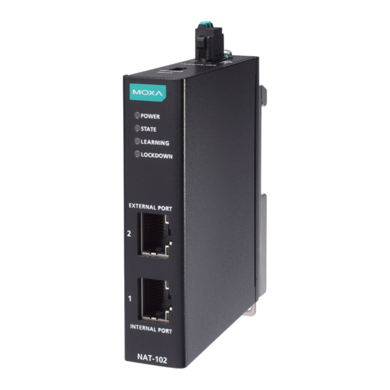
Package Checklist The NAT-102 Series, which is a NAT device, is shipped with the items listed below. If any of these items are missing or damaged, please contact your customer service representative for assistance. • 1 Industrial NAT device •... - Page 3 Panel Views of NAT-102 Series Front Panel Front Panel: 1. POWER LED indicator 2. STATE LED indicator 3. LEARNING LED indicator 4. LOCKDOWN LED indicator 5. 10/100 Mbps copper external port 6. 10/100 Mbps copper internal port Top Panel Top Panel: 1.
-
Page 4: Mounting Dimensions
DIN-rail Mounting In the package, the metal DIN-rail mounting kit is fixed to the back panel of the NAT-102 Series. Mount the NAT-102 Series on a corrosion- free mounting rail that adheres to the EN 60715 standard. - 4 -... -
Page 5: Wall Mounting
Series on the wall, as shown in the following illustrations. STEP 1: Remove the aluminum DIN-rail attachment plate from the rear panel of the NAT-102 Series, and then attach the wall mount plates with three M3 screws. - 5 -... -
Page 6: Wiring Requirements
STEP 2: Mounting the NAT-102 Series on the wall requires two M3 screws. Use the NAT-102 Series with the wall mount plates attached as a guide to mark the correct location of the two screws. Wiring Requirements WARNING Do not disconnect modules or wires unless power has been switched off or the area is known to be non-hazardous. -
Page 7: Wiring The Power Inputs
This product is intended to be mounted to a well-grounded mounting surface such as a metal panel. Wiring the Power Inputs The NAT-102 Series has one power input. The top and side views of the terminal block connector are shown below. STEP 1: Use a small flat-blade screwdriver to press a wire locker. -
Page 8: 10/100Baset(X) Ethernet Port Connection
2 10/100BaseT(X) Ethernet ports TYPE-C Console Port Connection The NAT-102 Series provides one TYBP-C console port located on the top panel. Connect the industrial secure router to a PC COM port using the Type-C-to-DB9 connection cable, and then launch a console terminal software, e.g. -
Page 9: Led Indicators
NOTE DO NOT power off the device when loading default settings. LED Indicators The front panel of the NAT-102 Series has several LED indicators. The function of each LED is described in the following table: Color State... -
Page 10: Standards And Certifications
Standards and Certifications WARNING 사 용 자 안 내 문 이 기기는 업무용 환경에서 사용할 목적으로 적합성 평가를 받은 기기로서 가정용 환경에서 사용하는 경우 전파간섭의 우려가 있습니다. ATEX information II 3 G Ex ec IIC T4 Gc UL 21 ATEX 2604X Ambient Range : -40 ℃...
Need help?
Do you have a question about the NAT-102 Series and is the answer not in the manual?
Questions and answers