
Related Manuals for Moxa Technologies NPort 5000 Series


Summary of Contents for Moxa Technologies NPort 5000 Series
- Page 1 NPort 5000 Series User’s Manual NPort 5000/5000A/IA5000/IA5000A Series Edition 2.1, October 2016 www.moxa.com/product © 2016 Moxa Inc. All rights reserved. www.ipc2u.ru www.ipc2u.ru www.moxa.pro www.moxa.pro...
-
Page 2: Copyright Notice
NPort 5000 Series User’s Manual The software described in this manual is furnished under a license agreement and may be used only in accordance with the terms of that agreement. Copyright Notice © 2016 Moxa Inc. All rights reserved. Trademarks The MOXA logo is a registered trademark of Moxa Inc. -
Page 3: Table Of Contents
Table of Contents About This Manual ..........................1-1 Getting Started..........................2-1 Installing Your NPort Device Server ....................... 2-2 Wiring Requirements ........................2-2 Connecting the Power ........................2-2 Grounding the NPort Device Server ....................2-2 Connecting to the Network ......................2-3 Connecting to a Serial Device ....................... - Page 4 COM Mapping ........................... 5-19 On-line COM Mapping ........................ 5-19 Off-line COM Mapping ........................ 5-24 COM Grouping ..........................5-25 Creating a COM Group ....................... 5-25 Deleting a COM Group........................ 5-27 Adding a Port to a COM Group ....................5-28 Removing a Port from a COM Group .................... 5-29 Modify Ports in a COM Group ......................
-
Page 5: About This Manual
NPort Family Model Series Introduction NPort 5000 NPort 5110/5130/5150 Series NPort 5000 series device servers are NPort 5210/5230/5232 Series designed to make serial devices NPort 5410/5430/5450 Series network-ready in an instant. The different NPort 5610/5630/5650 Series... -
Page 6: Getting Started
Getting Started In this chapter, we explain how to install a Moxa NPort device server for the first time. There are four ways to access the Moxa NPort’s configuration settings: Windows utility, web console, serial console, or Telnet console. The following table lists which NPort products support which configuration options. NPort Family NPort 5000/IA5000 NPort 5000A/IA5000A... -
Page 7: Installing Your Nport Device Server
NPort 5000 Series Getting Started Installing Your NPort Device Server This section describes how to connect an NPort device server to your serial devices for the first time. We cover Wiring Requirements, Connecting the Power, Grounding the NPort Device Server, Connecting to the Network, Connecting to a Serial Device, and LED Indicators. -
Page 8: Connecting To The Network
NPort 5000 Series Getting Started Type of Power Terminal Block Shielded Ground (SG) Applicable Products The Shielded Ground (sometimes called NPort IA5000 Series Protected Ground) contact is the left most contact of the 7-pin power terminal block connector when viewed from the angle shown here. -
Page 9: Led Indicators
NPort 5000 Series Getting Started LED Indicators NPort 5100/5100A/P5150A Series LED Name LED Color LED Function Ready Steady on: Power is on, and the NPort is booting up. Blinking: Indicates an IP conflict, or the DHCP or BOOTP server did not respond properly. - Page 10 NPort 5000 Series Getting Started NPort 5600 Series (Rackmount) LED Name LED Color LED Function Ready Steady on: Power is on and the NPort is booting up. Blinking: Indicates an IP conflict, or the DHCP or BOOTP server did not respond properly.
-
Page 11: Rs-485 Port's Adjustable Pull High/Low Resistor
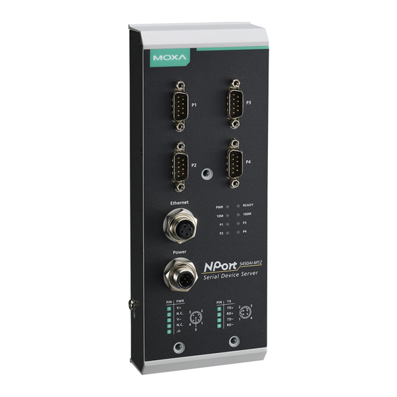
NPort 5000 Series Getting Started NPort 5000AI-M12 Series LED Name LED Color LED Function Green Power is being supplied to the power input. Ready Steady on: Power is on, and the NPort is booting up. Blinking: Indicates an IP conflict, or the DHCP or BOOTP server did not respond properly. -
Page 12: Configuration By Windows Utility
NPort 5000 Series Getting Started Configuration by Windows Utility NPort Administration Suite is an integrated software suite that bundles NPort Administrator and the IP Serial Library, providing everything you need to manage, monitor, and modify your NPort from a remote location. -
Page 13: Adjusting General Settings
NPort 5000 Series Getting Started In NPort Administrator, click Search to search your LAN for NPort device servers. When your unit appears in the search results, you may click Stop to end the search. You may also wait a few more moments for the search to complete. -
Page 14: Configuring Device Port Operation Mode
NPort 5000 Series Getting Started Static IP Addresses For most applications, you will assign a fixed IP address to the device server. To assign a static (fixed) IP address, the IP Configuration parameter must be set to Static, which is the default setting. You may then modify the IP Address and Netmask parameters. - Page 15 NPort 5000 Series Getting Started Set the operating mode and associated parameters as needed. Refer to Chapter 3 and Chapter 4 for additional information on operating modes and advanced settings. When you are ready to restart the device server with the new settings, click OK.
-
Page 16: Configuring Serial Communication Parameters
NPort 5000 Series Getting Started Configuring Serial Communication Parameters This section covers the configuration of each device port’s serial communication parameters: baudrate, stop bit, etc. Serial Parameter Review The following parameters need to be set correctly on the device port to ensure proper communication with your device. -
Page 17: Mapping Com Port To Device (Only Required When Operation Mode Is Set To Real Com Or Rfc2217)
NPort 5000 Series Getting Started The serial communication parameters for each device port can be configured through NPort Administrator. Open your device server’s configuration window, using the same method you used to configure network parameters. On the Serial screen, select the Modify check box and then select the device port that you wish to configure. - Page 18 NPort 5000 Series Getting Started A list of NPort device servers that have been found by NPort Administrator will appear. Select your device server and click Finish. Assigning COM Port Number to Device Port The COM Mapping screen shows a list of available device ports on the network. Right-click the target device port and select COM Settings in the pop-up menu.
-
Page 19: Advanced Settings
NPort 5000 Series Getting Started On the Serial Parameters screen, adjust the settings to match your device. These settings, which are only used for serial printers, must also match the settings on the device port. Click OK when you are satisfied with your changes. -
Page 20: Configuration By Web Console
NPort 5000 Series Getting Started Apply Change Right-click COM Mapping in the Function panel. Select Apply Change in the pop-up menu to save the current COM mapping settings. Your application will now be able to access the target serial device using the COM port. - Page 21 NPort 5000 Series Getting Started 2. Type 192.168.127.254 in the Address input box (use the correct IP address if different from the default), and then press Enter. 3. You will be prompted to enter the password to access the NPort web console. (The default password for NPort is moxa.)
- Page 22 NPort 5000 Series Getting Started The NPort homepage will open. On this page, you can see a brief description of the Web Console’s function groups. Web Interface for the NPort 5000 and NPort IA5000 Series Web Interface for the NPort 5000A and NPort IA5000A Series There are two buttons on this page: Quick setup and Export/Import.
-
Page 23: Quick Setup (Only For The Nport 5000A & Nport Ia5000A Series Web Console)
NPort 5000 Series Getting Started ATTENTION If you can’t remember the password, the ONLY way to start configuring the NPort is to load factory defaults by using the Reset button located near the NPort’s Ethernet port. Remember to use NPort Administrator (for NPort 5000 and NPort IA5000 Series) to export the configuration file when you have finished the configuration. - Page 24 NPort 5000 Series Getting Started Step 2/3 In Step 2/3, you must specify which operation mode you will use. If your operation mode is not Real COM, TCP Server, TCP Client, or UDP mode, click Cancel, return to the main menu, and choose Operating Settings to select the correct settings.
-
Page 25: Export/Import (Only For The Nport 5000A & Nport Ia5000A Series Web Console)
NPort 5000 Series Getting Started Finish Settings Review your settings on the Finish Settings page to confirm that they are correct and then click the Save/Restart button to restart the device with the new settings. NOTE If you change the IP address, you will not be able to use the Home button to return to the Home Page. -
Page 26: Basic Settings
NPort 5000 Series Getting Started Refer to the table below for the firmware versions that support the encrypted configuration files in the Web Console. Model Name Firmware version supporting encrypted configuration files. NPort 5100A Series Firmware v1.3 and up NPort 5200A Series Firmware v1.3 and up... - Page 27 NPort 5000 Series Getting Started NOTE The NPort 5150A does not support Time Settings. Parameter Setting Factory Default Description Necessity Server name 1 to 39 characters NP[model This option is useful for specifying Optional name]_[Serial the location or application of No.]...
-
Page 28: Network Settings
NPort 5000 Series Getting Started Network Settings Web Interface for the NPort 5000 and NPort IA5000 Series Web Interface for the NPort 5000A and NPort IA5000A Series You must assign a valid IP address to the NPort before it will work in your network environment. Your network system administrator should provide you with an IP address and related settings for your network. - Page 29 NPort 5000 Series Getting Started Method Function Definition Static The user must define the IP address, Netmask, and Gateway. DHCP The DHCP Server assigns the IP address, Netmask, Gateway, DNS, and Time Server DHCP/BOOTP The DHCP Server assigns the IP address, Netmask, Gateway, DNS, and Time Server, or the BOOTP Server assigns the IP address (if the DHCP Server does not respond).
-
Page 30: Snmp Settings
NPort 5000 Series Getting Started Parameter Setting Factory Default Description Necessity to access the host. The NPort provides DNS server 1 and DNS server 2 configuration items to configure the IP address of the DNS server. DNS Server 2 is included for use when DNS server 1 is unavailable. -
Page 31: Serial Settings
NPort 5000 Series Getting Started Parameter Setting Factory Description Necessity Default Auto report to E.g., 192.168.1.1 or None Reports generated by the Auto report Optional function will be automatically sent to this IP address. Auto report to E.g., 4001 4002... - Page 32 NPort 5000 Series Getting Started To modify serial settings for a particular port, click on the Port Number under Serial Settings, located under Main Menu on the left side of the browser window. Web Interface for the NPort 5000 and NPort IA5000 Series...
-
Page 33: Operating Settings
NPort 5000 Series Getting Started Parameter Setting Factory Description Necessity Default Parity None, Even, Odd, None Even and Odd parity provide rudimentary Required Space, Mark error-checking; Space and Mark parity are rarely used. Flow control None, RTS/CTS, RTS/CTS The method used to suspend and resume... - Page 34 NPort 5000 Series Getting Started Click on Operating Settings under Main Menu to display the operating settings for the NPort’s serial ports. To modify operating settings for a particular port, click on the Port Number under Operating Settings, located under Main Menu on the left side of the browser window.
- Page 35 NPort 5000 Series Getting Started Web Interface for the NPort 5000 and NPort IA5000 Series Web Interface for the NPort 5000A and NPort IA5000A Series 2-30 www.ipc2u.ru www.ipc2u.ru www.moxa.pro www.moxa.pro...
-
Page 36: Accessible Ip Settings
NPort 5000 Series Getting Started Accessible IP Settings Web Interface for the NPort 5000 and NPort IA5000 Series Web Interface for the NPort 5000A and NPort IA5000A Series Accessible IP Settings allow you to add or block remote host IP addresses to prevent unauthorized access. -
Page 37: Auto Warning Settings
NPort 5000 Series Getting Started • Any host can access the NPort Disable this function. Refer to the following table for more details about the configuration. Allowable Hosts Input format Any host Disable 192.168.1.120 192.168.1.120 / 255.255.255.255 192.168.1.1 to 192.168.1.254 192.168.1.0 / 255.255.255.0... - Page 38 NPort 5000 Series Getting Started Web Interface for the NPort 5000A and NPort IA5000A Series Mail Server Parameter Setting Factory Description Necessity Default Mail server IP or Domain None This optional field is for the IP address or Optional Name domain name of your network mail server, if applicable.
-
Page 39: Event Type
NPort 5000 Series Getting Started Event Type Web Interface for the NPort 5000 and NPort IA5000 Series Web Interface for the NPort 5000A and NPort IA5000A Series The Event Type parameters are used to configure which events will generate an automatic warning from the NPort device server, and how that warning will be issued. - Page 40 NPort 5000 Series Getting Started Authentication failure An authentication failure event is triggered when the user inputs an incorrect password from the Console or Administrator. When an authentication failure occurs, the NPort will immediately send an e-mail or SNMP trap.
- Page 41 NPort 5000 Series Getting Started Ethernet link down The NPort device server provides system maintainers with real-time alarm messages for Ethernet link down. Even when control engineers are out of the control room for an extended period of time, they can still be informed of the status of devices almost instantaneously when exceptions occur.
-
Page 42: Monitor
NPort 5000 Series Getting Started Monitor Monitor Line Click Line under Monitor to show the operation mode and status of each connection (IPx), for each of the four serial ports. Web Interface for the NPort 5000 and NPort IA5000 Series... - Page 43 NPort 5000 Series Getting Started Web Interface for the NPort 5000A and NPort IA5000A Series Monitor Async-Settings Click Async Setting under Monitor to show the run-time settings for each of the four serial ports. Web Interface for the NPort 5000 and NPort IA5000 Series...
-
Page 44: Change Password
NPort 5000 Series Getting Started Change Password You can set a password to restrict access to the NPort’s configuration parameters. (The default password for NPort is moxa.) If a user does not enter the correct password when accessing the NPort through one of the consoles (e.g., web console), access to the NPort configuration settings will be denied. -
Page 45: Load Factory Default
NPort 5000 Series Getting Started Load Factory Default Web Interface for the NPort 5000 and NPort IA5000 Series Web Interface for the NPort 5000A and NPort IA5000A Series This function will reset all of the NPort’s settings to the factory default values. Be aware that previous settings will be lost. - Page 46 NPort 5000 Series Getting Started 3. When the Telnet window opens, you will be prompted to input the Console password (the default password is moxa), input the password and then press Enter. 4. Type 2 to select Network settings, and then press Enter.
- Page 47 NPort 5000 Series Getting Started 6. Use the Backspace key to erase the current IP address, type in the new IP address, and then press Enter. 7. Press any key to continue… 2-42 www.ipc2u.ru www.ipc2u.ru www.moxa.pro www.moxa.pro...
- Page 48 NPort 5000 Series Getting Started 8. Type m and then press Enter to return to the main menu. 9. Type s and then press Enter to Save/Restart the system. 10. Type y and then press Enter to save the new IP address and restart the NPort.
-
Page 49: Configuration By Serial Console
NPort 5000 Series Getting Started Configuration by Serial Console Serial Console (19200, n, 8, 1) You may use the RS-232 console port to configure your NPort’s IP address. We suggest using PComm Terminal Emulator, which is available free of charge as part of the PComm Lite program suite, to carry out the installation procedure, although other similar utilities may also be used. - Page 50 NPort 5000 Series Getting Started 3. The Property window opens automatically. From the Communication Parameter page, select the appropriate COM port for the connection, COM1 in this example, and 19200 for Baud Rate, 8 for Data Bits, None for Parity, and 1 for Stop Bits.
- Page 51 NPort 5000 Series Getting Started 8. Input the password when prompted. The default password is moxa. 9. Start configuring the IP address under Network Settings. Refer to step 4 in the Telnet Console section for the rest of the IP settings.
-
Page 52: Testing Your Nport
NPort 5000 Series Getting Started Testing Your NPort After completing installation and configuration, you can do a simple test to ensure that your NPort will communicate successfully. Click on the appropriate link below to view a technical note that explains how to test your NPort one of four common operation modes: Real COM, TCP client, TCP server, and UDP. -
Page 53: Choosing The Proper Operation Mode
Choosing the Proper Operation Mode In this chapter, we describe the NPort device server’s various operation modes. The options include an operation mode that uses a driver installed on the host computer, and operation modes that rely on TCP/IP socket programming concepts. After choosing the proper operation mode in this chapter, refer to Chapter 4 for detailed configuration parameter definitions. -
Page 54: Overview
NPort 5000 Series Choosing the Proper Operation Mode Overview NPort serial device servers network-enable traditional RS-232/422/485 devices. A serial device server is a small computer equipped with a CPU, real-time OS, and TCP/IP protocols that can bi-directionally translate data between the serial and Ethernet formats. NPort device servers that are connected to a network that with access to the Internet can be accessed from a computer located anywhere in the world. -
Page 55: Rfc2217 Mode
NPort 5000 Series Choosing the Proper Operation Mode ATTENTION Real COM Mode allows several hosts to access the same NPort. The driver that comes with your NPort controls host access to attached serial devices by checking the host’s IP address. Refer to the Accessible IP Settings section in Chapter 2 for details. -
Page 56: Udp Mode
NPort 5000 Series Choosing the Proper Operation Mode UDP Mode Compared to TCP communication, UDP is faster and more efficient. In UDP mode, you can unicast or multicast data from the serial device to one or multiple host computers, and the... -
Page 57: Reverse Telnet Mode
NPort 5000 Series Choosing the Proper Operation Mode Reverse Telnet Mode Console management is commonly used by connecting to Console/AUX or COM ports of routers, switches, and UPS units. Rtelnet works the same as TCP Server mode in that only one TCP port is listened to after booting up. -
Page 58: Advanced Operation Mode Settings
Advanced Operation Mode Settings Your NPort’s serial ports can be configured to use one of several operation modes, such as Real COM mode or Reverse Telnet mode. In this chapter, we explain the settings for every parameter of every operation mode. The following topics are covered in this chapter: ... -
Page 59: Overview
NPort 5000 Series Advanced Operation Mode Settings Overview A device port’s operation mode determines how the port interacts with the network. Depending on your application and device, you may have the option of choosing between two or more operating modes. For each mode, the default settings should work for most applications. -
Page 60: Using Pair Connection Modes
NPort 5000 Series Advanced Operation Mode Settings Using Pair Connection Modes For some applications, you may want to configure two serial devices to communicate directly with each other over the network. This can be done with a pair of NPort device servers configured for Pair Connection Master/Slave modes. -
Page 61: Data Packing Parameters
NPort 5000 Series Advanced Operation Mode Settings Max connection Setting Options: 1 to 4 Default: 1 Description: Specifies the maximum number of simultaneous connections that the port will accept. When adjusting Max connection, make sure that Ignore jammed IP and Allow driver control are also configured correctly. - Page 62 NPort 5000 Series Advanced Operation Mode Settings Delimiter 1 and 2 Setting Options: Enable, 0 to FF Default: Disable Description: Controls data packing using special delimiter character(s). Serial data accumulates in the device port’s buffer until the delimiter character(s) are received, after which the data is packed for network transmission.
-
Page 63: Other Parameters
NPort 5000 Series Advanced Operation Mode Settings Other Parameters Local TCP port Setting Options: 1 to 65535 Default: 4001 for port 1, 4002 for port 2, etc. Description: Specifies the TCP port number for communicating with the attached device. - Page 64 NPort 5000 Series Advanced Operation Mode Settings Designated local port 1 through 4 Setting Options: 1 to 65535 Default: none Description: Specifies the TCP port number that will be used for data transmission with the device port. Local listen port ...
-
Page 65: Web Console
NPort 5000 Series Advanced Operation Mode Settings Web Console Click Operating Settings to display the operating settings for each of the NPort’s serial ports. Web Interface for the NPort 5000 and NPort IA5000 Series Web Interface for the NPort 5000A and NPort IA5000A Series www.ipc2u.ru... - Page 66 NPort 5000 Series Advanced Operation Mode Settings Real COM Mode Web Interface for the NPort 5000 and NPort IA5000 Series Web Interface for the NPort 5000A and NPort IA5000A Series www.ipc2u.ru www.moxa.pro...
- Page 67 NPort 5000 Series Advanced Operation Mode Settings Parameter Setting Factory Description Necessity Default 0 min: TCP connection is not closed due to an TCP Alive 0 to 99 min 7 min Optional Check Time idle TCP connection. 1 to 99 min: The NPort automatically closes the TCP connection if there is no TCP activity for the given time.
- Page 68 NPort 5000 Series Advanced Operation Mode Settings Parameter Setting Factory Description Necessity Default [Delimiter + 1] or [Delimiter + 2]: The data Delimiter Do nothing, Optional process Delimiter + 1, nothing will be transmitted when an additional byte (for Delimiter + 2,...
- Page 69 NPort 5000 Series Advanced Operation Mode Settings RFC2217 Mode Web Interface for the NPort 5000 and NPort IA5000 Series Web Interface for the NPort 5000A and NPort IA5000A Series 4-12 www.ipc2u.ru www.ipc2u.ru www.moxa.pro www.moxa.pro...
- Page 70 NPort 5000 Series Advanced Operation Mode Settings Parameter Setting Factory Description Necessity Default 0 min: TCP connection is not closed due to an TCP Alive 0 to 99 min 7 min Optional Check Time idle TCP connection. 1 to 99 min: The NPort automatically closes the TCP connection if there is no TCP activity for the given time.
- Page 71 NPort 5000 Series Advanced Operation Mode Settings NOTE Optimal force transmit timeout differs according to your application, but it must be at least larger than one character interval within the specified baudrate. For example, assume that the serial port is set to 1200 bps, 8 data bits, 1 stop bit, and no parity.
- Page 72 NPort 5000 Series Advanced Operation Mode Settings Web Interface for the NPort 5000A and NPort IA5000A Series Parameter Setting Factory Description Necessity Default TCP Alive 0 to 99 min 7 min 0 min: TCP connection is not closed due to an...
- Page 73 NPort 5000 Series Advanced Operation Mode Settings Parameter Setting Factory Description Necessity Default host by sending “keep alive” packets periodically. If the remote host does not respond to the packet, it assumes that the connection was closed down unintentionally. The NPort will then force the existing TCP connection to close.
- Page 74 NPort 5000 Series Advanced Operation Mode Settings Parameter Setting Factory Description Necessity Default Delimiter 1 00 to FF None Once the NPort receives both delimiters through Optional Delimiter 2 00 to FF None its serial port, it immediately packs all data Optional currently in its buffer and sends it to the NPort’s...
- Page 75 NPort 5000 Series Advanced Operation Mode Settings TCP Client Mode Web Interface for the NPort 5000 and NPort IA5000 Series 4-18 www.ipc2u.ru www.ipc2u.ru www.moxa.pro www.moxa.pro...
- Page 76 NPort 5000 Series Advanced Operation Mode Settings Web Interface for the NPort 5000A and NPort IA5000A Series Parameter Setting Factory Description Necessity Default TCP Alive 0 to 99 min 7 min 0 min: TCP connection is not closed due to an idle...
- Page 77 NPort 5000 Series Advanced Operation Mode Settings Parameter Setting Factory Description Necessity Default outgoing data through the serial port during the specific Inactivity time. If the inactivity time is set to 0, the current TCP connection is maintained until there is connection close request.
- Page 78 NPort 5000 Series Advanced Operation Mode Settings Parameter Setting Factory Description Necessity Default This parameter defines the time interval during which the NPort fetches the serial data from its internal buffer. If data is incoming through the serial port, the NPort stores the data in the internal buffer.
- Page 79 NPort 5000 Series Advanced Operation Mode Settings ATTENTION The Inactivity time should at least be set larger than that of Force transmit timeout. To prevent the unintended loss of data due to the session being disconnected, it is highly recommended that this value is set large enough so that the intended data transfer is completed.
- Page 80 NPort 5000 Series Advanced Operation Mode Settings Web Interface for the NPort 5000A and NPort IA5000A Series Parameter Setting Factory Description Necessity Default Packing length 0 to 1024 0: The Delimiter Process will be followed, Optional regardless of the length of the data packet.
- Page 81 NPort 5000 Series Advanced Operation Mode Settings Parameter Setting Factory Description Necessity Default This parameter defines the time interval during which the NPort fetches the serial data from its internal buffer. If data is incoming through the serial port, the NPort stores the data in the internal buffer.
- Page 82 NPort 5000 Series Advanced Operation Mode Settings Pair Connection Mode Pair Connection Mode employs two NPort device servers in tandem, and can be used to remove the 15-meter distance limitation imposed by the RS-232 interface. One NPort is connected from its RS-232 port to the COM port of a PC or other type of computer, such as a hand-held PDA, and the serial device is connected to the RS-232 port of the other NPort.
- Page 83 NPort 5000 Series Advanced Operation Mode Settings Parameter Setting Factory Description Necessity Default (E.g., default). Note that you must configure the 192.168.1.1) same TCP port No. for the device server acting TCP Port 4001 as the Pair Connection “Slave.” Required...
- Page 84 NPort 5000 Series Advanced Operation Mode Settings Ethernet Modem Mode (for the NPort IA5000/IA5000A, NPort 5000A, NPort 5000AI-M12, NPort 5100 series only) Web Interface for the NPort 5000 and NPort IA5000 Series Web Interface for the NPort 5000A and NPort IA5000A Series Dial-in The NPort listens for a TCP/IP connection request from the remote Ethernet modem or host.
- Page 85 NPort 5000 Series Advanced Operation Mode Settings NOTE The “+++” command cannot be divided. The “+” character can be changed in register S2, and the guard time, which prefixes and suffixes the “+++” in order to protect the raw data, can be changed in register S12.
- Page 86 NPort 5000 Series Advanced Operation Mode Settings S Register Description & default value Remarks Line feed character (default=10 ASCII) Backspace character (default= 8 ASCII) Wait time for dial tone (always=2, unit=sec) no action applied Wait time for carrier (default=3, unit=sec)
- Page 87 NPort 5000 Series Advanced Operation Mode Settings Web Interface for the NPort 5000A and NPort IA5000A Series Parameter Setting Factory Description Necessity Default TCP Alive 0 to 99 min 0 min Specifies the time slice for checking if the TCP...
- Page 88 NPort 5000 Series Advanced Operation Mode Settings Disabled Mode Web Interface for the NPort 5000 and NPort IA5000 Series Web Interface for the NPort 5000A and NPort IA5000A Series When Operation mode is set to Disabled, that particular port will be disabled. Select the Apply the above settings to all serial ports checkbox to apply this setting to the other ports.
-
Page 89: Configuring Nport Administrator
Configuring NPort Administrator The following topics are covered in this chapter: Overview Installing NPort Administrator Configuration Broadcast Search Unlock Password Protection Configuring NPort Upgrading the Firmware Export Configuration Import Configuration Monitor ... -
Page 90: Overview
NPort 5000 Series Configuring NPort Administrator Overview Device Server Administrator lets you install and configure your NPort device server easily over the network. Five function groups are provided to ease the installation process, allow off-line COM mapping, and provide monitoring and IP location server functions. - Page 91 NPort 5000 Series Configuring NPort Administrator 3. Click Next to install the program using the default program name, or select a different name. 4. Click Install to proceed with the installation. 5. The Installing window reports the progress of the installation.
- Page 92 NPort 5000 Series Configuring NPort Administrator 6. Click Next to proceed with the installation. 7. Click Finish to complete the installation of NPort Administration Suite. www.ipc2u.ru www.moxa.pro...
-
Page 93: Configuration
NPort 5000 Series Configuring NPort Administrator Configuration The Administrator-Configuration window is divided into four parts. • The top section contains the function list and online help area. (Windows NT does not support this .chm file format.) • The five Administrator function groups are listed in the left section. -
Page 94: Broadcast Search
NPort 5000 Series Configuring NPort Administrator Broadcast Search The Broadcast Search function is used to locate all NPort units that are connected to the same LAN as your computer. Since the Broadcast Search function searches by MAC address and not IP address, all NPort units connected to the LAN will be located, regardless of whether or not they are part of the same subnet as the host. -
Page 95: Unlock Password Protection
NPort 5000 Series Configuring NPort Administrator ATTENTION Before modifying the NPort’s configuration, use Broadcast Search to locate all NPort units connected to the LAN, or use Specify by IP Address to locate a particular NPort. Unlock Password Protection The NPort device server is password protected (the default password is moxa). The status of the NPort device will be indicated by "Lock."... -
Page 96: Configuring Nport
NPort 5000 Series Configuring NPort Administrator The meanings of the six “Status” states are given below (note that the term Fixed is borrowed from the standard fixed IP address networking terminology): Lock The NPort is password protected, “Broadcast Search” was used to locate it, and the password has not yet been entered from within the current Administrator session. -
Page 97: Upgrading The Firmware
NPort 5000 Series Configuring NPort Administrator 3. The progress bar shows that Administrator is retrieving configuration information from the specific NPort. 4. Refer to Chapter 2 for each parameter’s function definition. To modify the configuration, you must first click in the modify box to activate the parameter setting box. - Page 98 NPort 5000 Series Configuring NPort Administrator 2. Unlock the NPort you wish to configure. Right click a specific NPort and select the Upgrade Firmware function to start upgrading the firmware. 3. Select the correct ROM file to download. 4. Wait while the Upgrade Firmware action is processed.
-
Page 99: Export Configuration
NPort 5000 Series Configuring NPort Administrator Export Configuration The Export Configuration function is a handy tool that can be used to produce a text file that contains the current configuration of a particular NPort. To export the configuration of an NPort, right click NPort, select Export Configuration, and then an Export Password window will pop up for an user to assign a password for the exported configuration file (for the NPort Administration Suite v1.22 or above). -
Page 100: Import Configuration
NPort 5000 Series Configuring NPort Administrator Import Configuration The Import Configuration function is used to import an NPort configuration from a file into one or more of the same NPort model. To import a configuration, first select the target servers, click the right mouse button, and then select Import Configuration. - Page 101 NPort 5000 Series Configuring NPort Administrator You will be able to confirm the import content before downloading the file. Press OK to start downloading the configuration file. A window will pop up to indicate that import was successful. For firmware versions supporting encrypted configuration files, please refer to the table below.
-
Page 102: Monitor
NPort 5000 Series Configuring NPort Administrator Model Name Firmware version supporting encrypted configuration files. NPort 5000A/IA5000A Series Firmware v1.3 and up (Support with both web console and NPort NPort 5100A Series Administration Suite v1.22 or above) Firmware v1.3 and up (Support with both web console and NPort NPort 5200A Series Administration Suite v1.22 or above) - Page 103 NPort 5000 Series Configuring NPort Administrator Once the Monitor function is running: 1. The NPort list will appear on the Monitor screen. 2. Right click the panel and select Settings. 3. Select or de-select Monitor Items. Use the single arrowhead buttons to move highlighted items from one box to the other.
- Page 104 NPort 5000 Series Configuring NPort Administrator 4. Select a Refresh Rate (the default is 3 seconds) on the General Settings page. 5. On the Advanced Settings page, select Display warning message for new event and/or Play warning music for new event. In the second case, you must enter the path to the WAV file that you want to be played.
- Page 105 NPort 5000 Series Configuring NPort Administrator 6. Right click in the NPort list section and select Go to start Monitoring the NPort. 7. For this example, the NPort shown in the list will be monitored. 8. When one of the NPort units loses connection with the Monitor program, a warning alert will display automatically.
-
Page 106: Port Monitor
NPort 5000 Series Configuring NPort Administrator 10. If the NPort gets reconnected, a warning will be displayed to remind the user that the NPort is now “Alive.” 11. The NPort units that were reconnected, and are now “Alive,” will be shown in black color. -
Page 107: Com Mapping
NPort 5000 Series Configuring NPort Administrator Select or de-select Monitor Items. Use the single arrowhead buttons to move highlighted items from one box to the other. Use the double arrowhead buttons to move all items in one box to the other. - Page 108 NPort 5000 Series Configuring NPort Administrator 2. Select the COM Mapping function group. 3. Add the target to which you would like to map COM ports. 4. The NPort list that appears is the list generated by the previous Broadcast Search. Select the NPort to which you would like to map COM ports.
- Page 109 NPort 5000 Series Configuring NPort Administrator 6. Select the COM Number. COM ports that are “In use” or “Assigned” will also be indicated in this drop-down list. If you select multiple serial ports or multiple NPort units, remember to check the “Auto Enumerating” function to use the COM No.
- Page 110 NPort 5000 Series Configuring NPort Administrator Always Accept Open Requests: Even the driver cannot establish the connection to NPort, user's software still can open the mapped COM port just like a onboard COM port. Ignore TX Purge: The application can use Win32 API PurgeComm to clear the output buffer and terminate outstanding overlapped write operations.
- Page 111 NPort 5000 Series Configuring NPort Administrator 8. After setting the COM Mapping, remember to select Apply Change to save the information in the host system registry. The host computer will not have the ability to use the COM port until after Apply Change is selected.
-
Page 112: Off-Line Com Mapping
NPort 5000 Series Configuring NPort Administrator Off-line COM Mapping 1. Add a target by inputting the IP address and selecting the Model Name without physically connecting the NPort to the network. 2. Modify the port settings as needed. 3. Right click in the NPort list section and select Apply Change. -
Page 113: Com Grouping
NPort 5000 Series Configuring NPort Administrator COM Grouping The “COM Grouping” function is designed to simulate the multi-drop behavior of serial communication over an Ethernet network. COM Grouping allows you to create a COM Group and redirect data from it to several physical COM ports on NPort device servers. - Page 114 NPort 5000 Series Configuring NPort Administrator 3. Select the Grouping selected port(s) together checkbox. 4. On the COM Grouping page, you can set “Read” and “Write” permissions for every serial port. It is necessary to set Signal Status in order to control the data transmission with specified control signals (e.g., DTR/RTS).
-
Page 115: Deleting A Com Group
NPort 5000 Series Configuring NPort Administrator Deleting a COM Group Follow the steps below to delete a COM Group and then auto-assign COM numbers for each port in the Group: 1. Select all serial ports in the Group you are deleting and then right-click to select COM Settings. -
Page 116: Adding A Port To A Com Group
NPort 5000 Series Configuring NPort Administrator Adding a Port to a COM Group Follow the steps below to add a serial port into an existing COM Group: 1. Select the serial port that you are adding and right-click to select COM Settings. -
Page 117: Removing A Port From A Com Group
NPort 5000 Series Configuring NPort Administrator Removing a Port from a COM Group Follow the steps below to remove a serial port from a COM Group: 1. Select a serial port in the Group and right-click to select COM Settings. -
Page 118: Modify Ports In A Com Group
NPort 5000 Series Configuring NPort Administrator Modify Ports in a COM Group In the following subsections we examine three ways in which the serial ports in a COM Group can be modified: Changing the COM Number of a COM Group 1. - Page 119 NPort 5000 Series Configuring NPort Administrator 4. You will be able to view the serial ports that were assigned to and removed from the Group. Click Apply to apply the settings. 5. Finally, click Yes to confirm. Changing Advanced Settings and Serial Parameters of the COM Group 1.
- Page 120 NPort 5000 Series Configuring NPort Administrator 3. The Advanced Settings and Serial Parameters pages will be available for modification. Changing the Serial Port Specified as Signal Port for the COM Group 1. Select a serial port in the Group and then right-click and select COM Settings.
-
Page 121: Ip Address Report
NPort 5000 Series Configuring NPort Administrator 3. On COM Grouping page, you can specify one serial port whose signals will be taken into account by the COM Group and change the Read/Write status for each serial port. IP Address Report When the NPort is used in a dynamic IP environment, users must spend more time with IP management tasks. - Page 122 NPort 5000 Series Configuring NPort Administrator 2. Select the IP Address Report, and click the right mouse button to select Settings. 3. Configure the Local Listen Port to be the same as the NPort’s “Auto report to UDP port” setting.
-
Page 123: Nport Ce Driver Manager For Windows Ce
NPort CE Driver Manager for Windows CE NPort CE Driver Manager for Windows CE applies to the NPort 5000 and NPort IA5000 Series only. The following topics are covered in this chapter: Overview Installing NPort CE Driver Manager ... -
Page 124: Overview
NPort 5000 Series NPort CE Driver Manager for Windows CE Overview NPort CE Driver Manager is designed for use with NPort 5000 serial ports that are set to Real COM mode. The software manages the installation of drivers that allow you to map unused COM ports on your PC to serial ports on the NPort 5000. - Page 125 NPort 5000 Series NPort CE Driver Manager for Windows CE 2. Click on the COM Mapping page and then the “Search” button to scan for NPort servers 3. All NPort servers that were located will appear in the NPort CE Driver Manager window. Click on the server whose COM ports you would like to map to and then select the port index.
- Page 126 NPort 5000 Series NPort CE Driver Manager for Windows CE 6. To configure the settings for a particular COM Port, select the row of the desired port, and then modify the setting in the “Settings” panel, as shown below. Tx Mode “Hi-Performance”...
-
Page 127: Ip Serial Lib
IP Serial LIB The following topics are covered in this chapter: Overview What is IP Serial Library? Why Use IP Serial Library? How to Install IP Serial Library IP Serial LIB Function Groups Example Program www.ipc2u.ru www.ipc2u.ru www.moxa.pro... -
Page 128: Overview
NPort 5000 Series IP Serial LIB Overview What is IP Serial Library? IP Serial Library is a Windows library with frequently used serial command sets and subroutines. IP Serial Library is designed to reduce the complexity and poor efficiency of serial communication over TCP/IP. For example, Telnet can only transfer data, but it can’t monitor or configure the serial line’s parameters. -
Page 129: Ip Serial Lib Function Groups
NPort 5000 Series IP Serial LIB IP Serial LIB Function Groups Server Control Port Control Input/Output Data Port Status Miscellaneous Inquiry nsio_init nsio_open nsio_read nsio_lstatus nsio_break nsio_end nsio_close nsio_SetReadTimeouts nsio_data_status nsio_break_on nsio_resetserver nsio_ioctl nsio_write nsio_break_off nsio_checkalive nsio_flowctrl nsio_SetWriteTimeouts nsio_breakcount nsio_DTR... -
Page 130: Introduction To Lcm Display
Introduction to LCM Display Typically, you will use either NPort Administrator or the web console to configure the NPort 5600-8-DT series, NPort 5600 series (standard temperature models) and NPort 5410/5430 series (standard temperature models). These are not the only options for configuration. For basic onsite configuration, you can use the LCM console built into the device server, without requiring a connection to the network or a laptop. -
Page 131: Basic Operation
NPort 5000 Series Introduction to LCM Display Basic Operation If the NPort is working properly, the LCM panel will display a green color. The red Ready LED will also light up, indicating that the NPort is receiving power. After the red Ready LED turns to green, you will see a display... - Page 132 NPort 5000 Series Introduction to LCM Display • D = display only I.e., the setting for this option is displayed, but it cannot be changed (This does NOT necessarily mean that the number does not change; only that you cannot change it)
- Page 133 NPort 5000 Series Introduction to LCM Display The part of the LCM operation that still requires some explanation is how to edit the configurable options. In fact, you will only encounter two types of configurable options. The first type involves entering numbers, such as IP addresses, Netmasks, etc. In this case, you change the number one digit at a time.
-
Page 134: Pinouts And Cable Wiring
Pinouts and Cable Wiring The following topics are covered in this appendix: Port Pinout Diagrams Ethernet Port Pinouts Serial Port Pinouts Cable Wiring Diagrams Ethernet Cables Serial Cables www.ipc2u.ru www.moxa.pro... -
Page 135: Port Pinout Diagrams
NPort 5000 Series Pinouts and Cable Wiring Port Pinout Diagrams Ethernet Port Pinouts Ethernet RJ45 Ethernet M12 (For NPort 5000AI-M12 only) Ethernet M12: Signal Housing: shield Power M12: Description Input V+ Not assigned Input V- Not assigned Function ground Serial Port Pinouts... - Page 136 NPort 5000 Series Pinouts and Cable Wiring NPort 5130, NPort 5150, RS-422 / 4-wire 2-wire RS-485 NPort 5130A, NPort RS-485 5150A, NPort P5150A, TxD-(A) – NPort_5000AI-M12, TxD+(B) – NPort 5250A, NPort RxD+(B) Data+(B) 5450/5450I, 5650-8-DT, RxD-(A) Data-(A) 5650I-8-DT, 5650-8-DTL/DTL-T, and –...
- Page 137 NPort 5000 Series Pinouts and Cable Wiring NPort 5230 NPort 5230A, NPort IA5150, NPort IA5150A 2-wire RS-485 RS-422, 4-wire RS-485 – TxD+(B) – TxD-(A) Data+(B) RxD+(B) Data-(A) RxD-(A) NPort 5430/5430I Applies only to DT RJ45 Connector RS-232 models. www.ipc2u.ru www.ipc2u.ru www.moxa.pro...
-
Page 138: Cable Wiring Diagrams
NPort 5000 Series Pinouts and Cable Wiring NPort IA5150/5250 Shielded Relay Relay Ground Power Power output output Power Power input 1 input 1 input 2 input 2 NPort IA5000A PWR1 PWR2 RELAY Shielded DC Power DC Power Normal Open/Close, Relay... -
Page 139: Serial Cables
NPort 5000 Series Pinouts and Cable Wiring Serial Cables Serial Cable Wiring Diagrams www.ipc2u.ru www.ipc2u.ru www.moxa.pro www.moxa.pro... - Page 140 NPort 5000 Series Pinouts and Cable Wiring NPort 5210, NPort 5610/5650 (RS-232) www.ipc2u.ru www.moxa.pro...
- Page 141 NPort 5000 Series Pinouts and Cable Wiring NPort 5630 (RS-422/4-wire RS-485) www.ipc2u.ru www.ipc2u.ru www.moxa.pro www.moxa.pro...
- Page 142 NPort 5000 Series Pinouts and Cable Wiring NPort 5630 (2-wire RS-485) www.ipc2u.ru www.moxa.pro...
- Page 143 NPort 5000 Series Pinouts and Cable Wiring NPort 5650 (RS-422/4-wire RS-485) A-10 www.ipc2u.ru www.ipc2u.ru www.moxa.pro www.moxa.pro...
- Page 144 NPort 5000 Series Pinouts and Cable Wiring NPort 5650 (2-wire RS-485) A-11 www.ipc2u.ru www.moxa.pro...
- Page 145 NPort 5000 Series Pinouts and Cable Wiring Cable Wiring for NPort 5600-8-DT/DTL Series Serial Cable Wiring Diagrams NPort Serial Device RJ45 DB9(F) DB9(M) DB25(M) DB25(F) NPort Serial Device RJ45 DB9(F) DB9(M) DB25(M) DB25(F) TxD+ RxD+ TxD- RxD- RxD+ TxD+ RxD-...
- Page 146 NPort 5000 Series Pinouts and Cable Wiring Pin Assignments for DB9 and DB25 Connectors Pin Assignments for DB9 Male and Female Connectors DB9 Male Connector DB9 Female Connector Pin Assignments for DB25 Male and Female Connectors DB25 Male Connector DB25 Female Connector A-13 www.ipc2u.ru...
- Page 147 Adjustable Pull High/low Resistors for the RS-485 Port In some critical environments, you may need to add termination resistors to prevent the reflection of serial signals. When using termination resistors, it is important to set the pull high/low resistors correctly so that the electrical signal is not corrupted.
-
Page 148: Adjustable Pull High/Low Resistors For The Rs-485 Port
NPort 5000 Series Adjustable Pull High/low Resistors for the RS-485 Port NPort 5130A/5150A (Jumpers) To set a pull high/low resistor to 150 kΩ, make sure that the two jumpers (JP3 and JP4) assigned to the serial port are not shorted by jumper caps. This is the default setting. - Page 149 NPort 5000 Series Adjustable Pull High/low Resistors for the RS-485 Port NPort 5400 Series (DIP Switches) To set the pull high/low resistors to 150 KΩ, make sure both of the assigned DIP switches are in the OFF position. This is the default setting.
- Page 150 NPort 5000 Series Adjustable Pull High/low Resistors for the RS-485 Port NPort 5600-8-DT/DTL Series (DIP Switches) NPort 5600-8-DT: Use the DIP switches on the bottom panel to configure each device port’s pull high/low resistors. You will need to unscrew the DIP switch cover to access the DIP switches.
- Page 151 NPort 5000 Series Adjustable Pull High/low Resistors for the RS-485 Port NPort IA5000 Series When setting up your RS-485 and RS-422 networks, you should use termination resistors to prevent signal reflections. The NPort IA5000 Series does not come with pull high/low resistors and terminators, so you will need to obtain and configure the termination yourself.
- Page 152 NPort 5000 Series Adjustable Pull High/low Resistors for the RS-485 Port NPort IA5000A Series (DIP Switches) The DIP switches are located on the PCB board; you will need to take off the covers to access them. To set the pull-high resistor to 150 KΩ, flip DIP1 to “OFF,” and then set the pull-low resistor to 150 KΩ, and then flip DIP2 to “OFF.”...
-
Page 153: Well-Known Port Numbers
Well-Known Port Numbers In this appendix, which is included for your reference, we provide a list of well-known port numbers that may cause network problems if you set the NPort to one of these ports. Refer to RFC 1700 for well-known port numbers, or refer to the following introduction from the IANA. - Page 154 NPort 5000 Series Well Known Port Numbers UDP Socket Application Service reserved Management Utility Echo Discard Active Users (systat) Daytime Any private printer server Resource Location Protocol Host name server (names server) Whois (nickname) (Login Host Protocol) (Login) Domain Name Server (domain)
-
Page 155: Snmp Agents With Mib Ii & Rs-232/422/485 Link Groups
SNMP Agents with MIB II & RS-232/422/485 Link Groups The NPort has built-in SNMP (Simple Network Management Protocol) agent software. It supports SNMP Trap, RFC1317 RS-232 like group and RFC 1213 MIB-II. The following table lists the standard MIB-II group, as well as the variable implementation for the NPort device server. - Page 156 NPort 5000 Series SNMP Agents with MIB II & RS-232/422/485 Link Groups UDP MIB TCP MIB SNMP MIB UdpInDatagrams tcpRtoAlgorithm snmpInPkts UdpNoPorts tcpRtoMin snmpOutPkts UdpInErrors tcpRtoMax snmpInBadVersions UdpOutDatagrams tcpMaxConn snmpInBadCommunityNames UdpLocalAddress tcpActiveOpens snmpInASNParseErrs UdpLocalPort tcpPassiveOpens snmpInTooBigs tcpAttempFails snmpInNoSuchNames Address Translation MIB...
-
Page 157: Auto Ip Report Protocol
Auto IP Report Protocol The NPort Series provides several ways to configure Ethernet IP addresses. One of them is DHCP Client. When you set up the NPort to use DHCP Client to configure Ethernet IP addresses, it will automatically send a DHCP request over the Ethernet to find the DHCP Server. - Page 158 NPort 5000 Series Auto IP Report Protocol ID List ID Value Description Length Note Server Name Variable ASCII char Hardware ID Little-endian MAC Address 6 bytes MAC address. If the MAC address is "00-90-E8-01-02-03", the MAC[0] is 0, MAC[1] is 0x90(hex), MAC[2] is 0xE8(hex), and so on.
- Page 159 NPort 5000 Series Auto IP Report Protocol AP ID & Hardware ID Mapping Table AP ID Device ID Product 0x80015100 0x511A NPort 5110A 0x80015100 0x513A NPort 5130A 0x80015100 0x515A NPort 5150A 0x80015200 0x521A NPort 5210A 0x80015200 0x523A NPort 5230A 0x80015200...
-
Page 160: Compliance Notice
Compliance Notice CE Warning This is a Class A product. In a domestic environment, this product may cause radio interference, in which case the user may be required to take appropriate measures. Federal Communications Commission Statement This device complies with part 15 of the FCC Rules. Operation is subject to the following two conditions: (1) This device may not cause harmful interference, and (2) this device must accept any interference received, including interference that may cause undesired operation.
Need help?
Do you have a question about the NPort 5000 Series and is the answer not in the manual?
Questions and answers