Table of Contents

Subscribe to Our Youtube Channel
Related Manuals for Moxa Technologies EDR-G9004 Series


Summary of Contents for Moxa Technologies EDR-G9004 Series
- Page 1 EDR-G9004 Series Quick Installation Guide Moxa Industrial Secure Router Version 1.0, May 2024 Technical Support Contact Information www.moxa.com/support 2023 Moxa Inc. All rights reserved. P/N: 1802090040010 *1802090040010*...
-
Page 2: Package Checklist
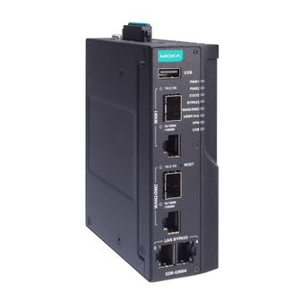
Package Checklist The EDR-G9004 Series secure router is shipped with the items listed below. If any of these items are missing or damaged, please contact your customer service representative for assistance. • 1 Industrial secure router • 1 USB-C-to-DB9 cable •... - Page 3 Panel Views of EDR-G9004 Series EDR-G9004 Series Front Panel Front Panel: 1. USB port for ABC-02-USB 2. 1G/2.5G SFP port speed LED indicator 3. 1G/2.5G SFP ports 4. 10/100/1000 Mbps copper port speed LED indicator 5. 10/100/1000 Mbps copper ports 6.
- Page 4 Rear Panel Rear Panel: 1. DIN-rail mounting kit - 4 -...
-
Page 5: Mounting Dimensions
DIN-rail Mounting In the package, the metal DIN-rail mounting kit is fixed to the back panel of the EDR-G9004 Series with four screws (M3 x 6 mm). Mount the EDR-G9004 Series on a corrosion-free mounting rail that adheres to the EN 60715 standard. -
Page 6: Wall Mounting
G9004 Series on the wall, as shown in the following illustrations. STEP 1: Remove the aluminum DIN-rail attachment plate from the rear panel of the EDR-G9004 Series, and then attach both the wall- mounting plates with six screws (M3 x 5 mm). -
Page 7: Wiring Requirements
STEP 2: Mounting the EDR-G9004 Series on the wall requires four screws. Use the EDR-G9004 Series with the wall mount plates attached as a guide to mark the correct location of the four screws. The head of the screws should be less than 7.0 mm in diameter, and the shaft should be less than 3.5 mm in diameter. - Page 8 ATTENTION Safety First! Be sure to disconnect the power cord before installing and/or wiring your EDR-G9004 Series. Calculate the maximum possible current in each power wire and common wire. Observe all electrical codes dictating the maximum current allowable for each wire size.
-
Page 9: Wiring The Redundant Power Inputs
Wiring the Redundant Power Inputs The EDR-G9004 Series has two sets of power inputs—power input 1 and power input 2. The top and side views of the terminal block connector are shown below. The input terminal block (TB1) should be installed using 16-24 AWG wires. -
Page 10: The Reset Button
A6, B6 A7, B7 10/100/1000BaseT(X) Ethernet Port Connection The 10/100/1000BaseT(X) ports located on the EDR-G9004 Series front panel are used to connect to Ethernet-enabled devices. Most users will choose to configure these ports for Auto MDI/MDI-X mode, in which case the port’s pinouts are adjusted automatically depending on the type of Ethernet cable used (straight-through or cross-over) and the type of device (NIC-type or HUB/Switch-type) connected to the port. -
Page 11: Led Indicators
NOTE DO NOT power off the device when loading default settings. LED Indicators The front panel of the EDR-G9004 Series has several LED indicators. The function of each LED is described in the following table: Color State Description Power is being supplied to power input P1 on the main module. - Page 12 Input Voltage 12 to 48 VDC, dual power input Power Consumption 12.96 W (max.) Operating Temperature Standard models: -10 to 60°C (14 to 140°F) Wide-temp. models: -40 to 75°C (-40 to 167°F) Storage Temperature -40 to 85°C (-40 to 185°F) WARNING 사...
Need help?
Do you have a question about the EDR-G9004 Series and is the answer not in the manual?
Questions and answers