Table of Contents
Advertisement
Quick Links
Advertisement
Table of Contents

Related Manuals for Moxa Technologies SDS-3006 Series


Summary of Contents for Moxa Technologies SDS-3006 Series
- Page 1 SDS-(G)3006/SDS-(G)3008 Series Quick Installation Guide Moxa’s Industrial Smart Ethernet Switch Version 4.0, September 2024 Technical Support Contact Information www.moxa.com/support 2024 Moxa Inc. All rights reserved. P/N: 1802300800015 *1802300800015*...
-
Page 2: Package Checklist
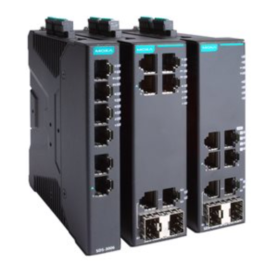
Overview The SDS-(G)3000 industrial smart Ethernet switch is the ideal device for IA engineers and automation machine builders to make their networks compatible with the vision of Industry 4.0. By breathing life into machines and control cabinets, the smart switch simplifies daily tasks with its easy configuration and installation. - Page 3 SDS-(G)3006/(G)3008 Panel Layout Front Panel 1. 10/100/1000BaseT(X) ports 2. 10/100BaseT(X) ports 3. System LEDs: STATE (S), FAULT (F), PWR1 (P1), PWR2 (P2) 4. Port LEDs 5. Model name 1. 10/100/1000BaseT(X) ports 2. 10/100BaseT(X) ports 3. 10/100/1000BaseT(X) or 100/1000BaseSFP combo ports 4.
- Page 4 Top Panel 1. Ground connector screw 2. Terminal blocks for power input, digital input, and relay output 3. USB storage port (type A connector) 4. Reset button Side Panel 1. DIN-rail mounting kit 2. Screw hole (used for sideways DIN-rail mounting options) - 4 -...
-
Page 5: Mounting Dimensions
Bottom Panel 1. Rotary DIP switch for EtherNet/IP, PROFINET, Modbus/TCP, and DHCP Client configurations Mounting Dimensions SDS-(G)3006/SDS-(G)3008 Models - 5 -... -
Page 6: Din Rail Mounting
SDS-(G)3006-2GTXSFP Models DIN-rail Mounting The SDS-(G)3000 Series supports two options for DIN-rail mounting. ATTENTION In order to ensure reliable operations, please make sure the operating temperature of the environment does not exceed the specification. When mounting the SDS-(G)3000 Series with other operating units in a cabinet without forced ventilation, a minimum spacing of 5 cm on both sides and above/below the switch is recommended. -
Page 7: Installation
Installation STEP 1—Insert the DIN rail into the upper lip of the DIN- rail kit. STEP 2—Press the SDS- (G)3000 towards the DIN rail until it snaps into place. Removal STEP 1—Pull down the latch on the DIN-rail mounting kit with a screwdriver. -
Page 8: Wall Mounting (Optional)
STEP 2—Insert DIN-rail into the upper lip of the DIN-rail kit. STEP 3—Press the SDS-(G)3000 towards the DIN rail until it snaps into place. Removal STEP 1—Pull down the latch on the DIN-rail mounting kit with a screwdriver. STEPS 2—Slightly pull the SDS- (G)3000 backwards. - Page 9 ATTENTION In order to ensure reliable operations, please make sure the operating temperature of the environment does not exceed the specification. When mounting the SDS-(G)3000 Series with other operating units in a cabinet without forced ventilation, a minimum spacing of 5 cm on both sides and above/below the switch is recommended.
-
Page 10: Wiring Requirements
Removal STEP 1—Pull down the latch on the DIN-rail mounting kit with a screwdriver. STEP 2—Slightly pull the SDS-(G)3000 backwards. STEP 3—Lift the device up to remove it from the wall-mounting kit. Wiring Requirements ATTENTION Safety First! Be sure to disconnect the power cord before installing and/or wiring your Moxa Industrial Smart Ethernet Switch. -
Page 11: Wiring The Relay Contact
Suggested Wire Type for Wiring Relay Contact (R), Digital Input (DI), and Power Inputs (P1/P2) The switch includes two 4-pin 3.5 mm pin-pitch terminal blocks. When wiring the relay contact (R), digital input (DI) and power inputs (P1/P2) for the SDS-(G)3000 Series, we suggest using the cable type AWG (American Wire Gauge) 18 to 24 and the corresponding pin type cable terminals. - Page 12 Refer to the instructions and diagram below on how to connect the wires to the terminal block connector, and how to attach the terminal block connector to the terminal block receptor. STEP 1—Insert two wires into the relay position (see the diagram below showing the top view) on the terminal.
-
Page 13: Wiring The Redundant Power Inputs
Refer to the instructions and diagram (top view) below on how to connect the wires to the terminal block connector, and how to attach the terminal block connector to the terminal block receptor. STEP 1: Insert the negative (ground)/positive DI wires into the respective ┴/I terminals. -
Page 14: Communication Connections
ATTENTION Only use a certified power supply with SELV output or a certified power supply that provides double insulation in accordance with one of the following standards: • UL 60950-1 • UL 62368-1 • UL 61010-1 and UL 61010-2-201 The assembler of the system is responsible for the safety of the system incorporating the SDS-3000/G3000 Series. - Page 15 NOTE ABC-02-USB Installation Plug the ABC-02-USB into the USB storage port of the SDS-(G)3000 Series. We suggest securing the ABC-02-USB on the wall with an M4 screw. 10/100BaseT(X) Ethernet Port Connections The 10/100BaseT(X) ports located on the front panel of the switch are used to connect to Ethernet-enabled devices.
- Page 16 10/100/1000BaseT(X) Ethernet Port Connections 1000BaseT(X) data is transmitted on differential TRD+/- signal pairs over copper wires. MDI Port Pinouts 8-pin RJ45 Signal TRD(0)+ TRD(0)- TRD(1)+ TRD(2)+ TRD(2)- TRD(1)- TRD(3)+ TRD(3)- RJ45 (8-pin) to RJ45 (8-pin) Straight-through Cable Wiring RJ45 (8-pin) to RJ45 (8-pin) Cross-over Cable Wiring 100/1000BaseSFP Port Connections The fiber ports on the switch are 100/1000BaseSFP fiber ports, which require using 100M or 1G mini-GBIC fiber transceivers to work...
-
Page 17: Rotary Dip Switch
Consequently, one of the optical lines is used to transmit data from device A to device B, and the other optical line is used transmit data from device B to device A, for full-duplex transmission. Remember to connect the Tx (transmit) port of device A to the Rx (receive) port of device B, and the Rx (receive) port of device A to the Tx (transmit) port of device B. -
Page 18: Reset Button
Rotary DIP Switch Settings for IA Profiles Indicator Mode No function enabled via DIP switch (default) PROFINET profile enabled PROFINET profile and DHCP Client enabled EtherNet/IP profile enabled EtherNet/IP profile and DHCP Client enabled Modbus TCP profile enabled Modbus TCP profile and DHCP client enabled Reserved (currently performs the same behavior as indicator 0) Reset Button... - Page 19 Color Status Description The system failed self-diagnosis on boot-up: Failed to read system information or EEPROM information error. FAULT 1. The relay contact has been triggered. 2. Invalid port connection. 3. Failed to load from or save to the ABC-02. Blinking 1.
-
Page 20: Specifications
Color Status Description Per 100/1000 Mbps SFP Port LED 1000M Green When the port is active and links at 1000 Mbps. Blinking When the port’s data is being transmitted at 1000 Mbps. When the port is inactive or link down. 100M Amber When the port is active and links... - Page 21 Digital Input 1 input with the same ground, but electrically isolated from the electronics. • +13 to +30 V for state “1” • -30 to +3 V for state “0” • Max. input current: 8 mA Button Reset button Power Requirements Input Voltage 12 to 48 VDC, redundant dual inputs Operating Voltage...
- Page 22 IEC 61000-4-8 PFMF: Level 3 Shock IEC 60068-2-27 Freefall IEC 60068-2-32 Vibration IEC 60068-2-6 Warranty Warranty Period 5-years Details See www.moxa.com/warranty ATTENTION This device complies with Part 15 of the FCC rules. Operation is subject to the following conditions: 1. This device may not cause harmful interference. 2.
Need help?
Do you have a question about the SDS-3006 Series and is the answer not in the manual?
Questions and answers