
Related Manuals for Sony PXW-Z450


Summary of Contents for Sony PXW-Z450
- Page 1 4-693-039-12 (1) Solid-State Memory Camcorder Operating Instructions PXW-Z450 Software Version 2.0 © 2016 Sony Corporation...
-
Page 2: Table Of Contents
000 2 Table of Contents Connecting Devices using Wireless LAN ......58 Connecting an External Monitor ........124 1. Overview Connecting to the Internet ..........62 Managing/Editing Clips with a Computer ....125 Name and Function of Parts ..........3 Transferring Files ..............65 Configuring a Shooting and Recording System ....127 Screen Display ..............13 Transmitting Streaming Video and Audio ......67 Recording External Input Signals........130... -
Page 3: Overview
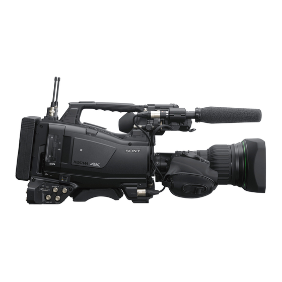
AC power supply. “Preparing a Power Supply” (page 20) [Note] For your safety, and to ensure proper operation of the camcorder, Sony recommends the use of the BP-FLX75 Battery Pack. Camera adaptor connector Enables connection of a CA-TX70/FB70 HD Camera Adaptor. - Page 4 1. Overview: Name and Function of Parts this connector, power off the camcorder first. Accessory Attachments Controls Near the Lens Lens mount securing rubber After locking the lens in position using the lens locking lever, fit this rubber over the lower of the two projections.
- Page 5 1. Overview: Name and Function of Parts [Note] AUTO W/B BAL (automatic white/black LCD Monitor Side (1) If Flash Band Reduce is On, setting the SHUTTER switch balance adjustment) switch to ON turns off the Flash Band Reduce function and the Activates the automatic white/black balance FBR indicator disappears from the viewfinder screen.
- Page 6 1. Overview: Name and Function of Parts ASSIGN. (assignable) 1/2/3 switches MONITOR (audio monitor selection) switches OUTPUT/DCC (output signal/dynamic Examples: ˎ When a single color dominates the subject, such as sky, ˎ You can assign a function using Operation By means of combinations of the two switches, contrast control) switch sea, ground, or flowers.
- Page 7 1. Overview: Name and Function of Parts this switch up to this position again resets the Built-in speaker LCD Monitor Side (2) settings to the initial value. The speaker can be used to monitor E-E sound ESCAPE: Use this switch when the menu page, during recording, and playback sound during which has a hierarchical structure, is opened.
- Page 8 1. Overview: Name and Function of Parts PLAY/PAUSE button and indicator Display indication Description Switch settings RESET/RETURN button Press this button to view playback video images operation Video without Only the video appears. using the viewfinder screen or the LCD monitor. superimposed DISPLAY switch: Reset user bits data...
- Page 9 1. Overview: Name and Function of Parts Thumbnail screen operations section and audio control section ESSENCE MARK button AUDIO IN CH1/CH2/CH3/CH4 (audio channel By pressing this button when a thumbnail display 1/2/3/4 input selection) switches is on the screen, you can view the following Select the audio input signals to be recorded on thumbnail displays of the essence-marked frames audio channels 1, 2, 3 and 4.
- Page 10 1. Overview: Name and Function of Parts “Obtaining Location Information (GPS)” (page 56) Network connector Handle and Memory Card Slot Side Connects to a network via a wired LAN connection [Note] using a LAN cable (sold separately). Do not grasp this part of the camcorder when the GPS function is in use.
- Page 11 1. Overview: Name and Function of Parts TC OUT (timecode output) connector (BNC TALLY (back tally) indicator (red) Tally Indicator and Connector Section type) Lights up during recording. It will not light if the To lock the timecode of an external VTR to TALLY switch is set to OFF.
- Page 12 1. Overview: Name and Function of Parts AUDIO IN CH-1/CH-2 (audio channel 1 and channel 2 input) connectors (XLR type, 3-pin, female) Connect to audio equipment or a microphone. Bottom cover This is provided for protecting the cables connected to the connectors on the rear panel. By loosening the screws which retain the cover to the bottom of the camcorder, you can adjust the position of the cover depending on the size and...
-
Page 13: Screen Display
1. Overview Screen Display Clip name display CANCEL/PRST/ESCAPE switch up to the CANCEL/ Information Screen Displays the name of the clip currently recording PRST position to display the status screen. Each when recording, or displays the name of the next push selects the next status screen. - Page 14 1. Overview: Screen Display Audio Status screen Display item Description Display item Description Rec Function Enabled special recording format NW Client Network client mode status Displays settings and status information related to and settings Mode Status For details about the status, see audio input and output.
- Page 15 1. Overview: Screen Display Status State Description Status State Description Display item Description display display Supplied Supplied power source voltage Connecting Connecting to Attempting to Cert. not The CCM certificate Voltage connect to CCM (or Valid certification not is not valid. The date (disconnected) disconnecting).
- Page 16 1. Overview: Screen Display superimposed on the display. signal level by the number of gray segment Viewfinder Screen Indicator Meaning You can toggle the display of information on/off indicators. Cont Stby Recording standby in clip continuous using the DISPLAY switch. If the received level exceeds the peak: Displays “P”...
- Page 17 1. Overview: Screen Display Wired LAN connection status The following icons are displayed when streaming State Icon Menu settings Indicator Displays the wired LAN network setting and from a CCM. Operation Maintenance Network Operation Paint >Gamma setting >Display >Network connection connection status using icons.
- Page 18 1. Overview: Screen Display Time data display Icon Media state Icon Meaning during proxy file transfer. When transfer finishes, Displays the remaining recording/playback disappears to indicate 100% transfer. – Media not inserted or not mounted Spotlight mode time, timecode, user bits, etc., as selected by the Network client mode indicator DISPLAY switch (page 8).
- Page 19 1. Overview: Screen Display 5600K: Appears when an assignable switch assigned with Color Temp SW 5600K is on 6300K: Appears when an assignable switch assigned with Color Temp SW 6300K is on...
-
Page 20: Preparation
000 20 2. Preparation Preparing a Power Supply For safety, use only the Sony battery packs and AC For details on the battery charging procedure, refer to the battery charger operation manual. adaptors listed below. ˎ BP-FLX75 Lithium-ion Battery Pack ˎ... -
Page 21: Attaching A Viewfinder
2. Preparation Attaching a Viewfinder [CAUTION] the way so that your right leg does not hit the Couple the viewfinder connector to the VF When the viewfinder is attached, do not leave the camcorder viewfinder while you are carrying the camcorder. connector (26-pin). - Page 22 2. Preparation: Attaching a Viewfinder Bolts supplied with the BKW-401 Adjust the front-to-back position so that the arm of the BKW-401 does not touch the handle when it is raised. Adjust position so that arm does not touch handle...
-
Page 23: Using The Camcorder For The First Time
2. Preparation Using the Camcorder for the First Time When using the camcorder for the first time, Turn the MENU knob to set the year, month, or configure the following settings in the menu. day, and then press the knob. For details about menu operations, see “Basic Setup Menu Operations”... -
Page 24: Mounting And Adjusting The Lens
Place the supplied flange focal length Contact a Sony service representative for adjustment chart about 3m (10 ft) in front of information about aberration correction lenses. -
Page 25: Preparing The Audio Input System
Attaching a Wireless Receiver For the procedure for attaching to a viewfinder, refer to the manual supplied with the viewfinder. To use a Sony wireless microphone system, power Loosen the screw and open the microphone the camcorder off and then attach a wireless holder clamp. -
Page 26: Attaching And Adjusting Peripheral Devices
2. Preparation Attaching and Adjusting Peripheral Devices [Note] Mounting on a Tripod Attaching the Shoulder Strap The tripod adaptor pin may remain in the engaged position even after the camcorder is removed. If this happens, press the red button and move the lever as shown above until the pin returns to the stowed position. -
Page 27: Handling Sxs Memory Cards
Open the cover, and then press the EJECT Use Sony SxS memory cards (SxS PRO+, SxS PRO, [Note] or SxS-1) with this camcorder. button to release the lock and extract the... - Page 28 2. Preparation: Handling SxS Memory Cards [Notes] message. You can check the remaining capacity on a bar If restoration fails ˎ The SLOT SELECT button is disabled during playback. The ˎ graph by displaying the Media Status screen memory cards are not switched even if you press the If formatting fails (page 15).
-
Page 29: Handling Sd Cards For Saving Configuration Data
2. Preparation Handling SD Cards for Saving Configuration Data The following SD cards can be used for saving Checking the Remaining Capacity configuration data. SDHC memory cards* (Speed Class: 4 to 10, non- You can check the remaining capacity on an SD UHS, Capacity: 4 to 32 GB) card on the Media Status screen (page 15). -
Page 30: Using A Media Adaptor
USB cable. Formatting (initializing) that was formatted in a different specification is XQD is a registered trademark of Sony inserted, a message asking for confirmation to To use a memory card formatted on the Corporation. -
Page 31: Settings And Adjustments
000 31 3. Settings and Adjustments Format Settings You can set the file system, system frequency, and video format using Operation >Format in the setup Switching the Video Format menu. For details about menu operations, see “Basic Setup Menu Operations” (page 85). Refer to “Video Formats”... - Page 32 3. Settings and Adjustments: Format Settings Video Formats VIDEO Connector Output Formats The following recording formats can be selected for different combinations of video resolution and The signals that can be output from the VIDEO connector are shown in the following table according to system frequency.
- Page 33 3. Settings and Adjustments: Format Settings Operation menu VIDEO OUT signal format Operation menu VIDEO OUT signal format Format Format Frequency Rec Format (codec omitted) Proxy recording/Wireless LAN connection function Frequency Rec Format (codec omitted) Proxy recording/Wireless LAN connection function 23.98 3840×2160P HD-Sync...
- Page 34 3. Settings and Adjustments: Format Settings SDI OUT Connector and HDMI Output Connector Output Formats The signals that can be output from the SDI OUT connectors and HDMI output connectors are shown in the following table according to the Operation >Format setting in the setup menu. Up to two lines are available when the signal output from the SDI OUT1 to 4 connectors is Dual Link output, and up to four lines when the signal output is Single output.
- Page 35 3. Settings and Adjustments: Format Settings Operation >Format in the Operation >Input/Output >Output Format in the Output signal format setup menu setup menu Frequency Rec Format SDI Out1/3 Output HDMI Output SDI OUT 1 to 4 connectors HDMI connector (codec omitted) or SDI Out2/4 Output 29.97 3840×2160P...
- Page 36 3. Settings and Adjustments: Format Settings Operation >Format in the Operation >Input/Output >Output Format in the Output signal format setup menu setup menu Frequency Rec Format SDI Out1/3 Output HDMI Output SDI OUT 1 to 4 connectors HDMI connector (codec omitted) or SDI Out2/4 Output 1920×1080i 1920×1080i...
-
Page 37: Adjusting The Black Balance And White Balance
3. Settings and Adjustments Adjusting the Black Balance and White Balance To ensure excellent image quality when using this The message “Executing…” appears during The message “Executing…” appears during Set the switches and selectors as shown camcorder, conditions may require that both the execution, and changes to “OK”... - Page 38 3. Settings and Adjustments: Adjusting the Black Balance and White Balance White balance memory Error message Meaning Turn the MENU knob to select the desired NG: Out of Range Value could not be adjusted color temperature. Values stored in memory are held until the white because the difference balance is next adjusted, even if the camcorder between the current value and...
-
Page 39: Setting The Electronic Shutter
3. Settings and Adjustments Setting the Electronic Shutter ECS (Extended Clear Scan) mode ˎ The selectable shutter speeds vary depending on the ˎ Setting the shutter speed (ECS mode) Shutter Modes current system frequency. Select this mode for obtaining images with no Switching between Speed mode and Angle mode Set the shutter mode to ECS (see the previous horizontal bands of noise when shooting subjects... -
Page 40: Setting Auto Iris
3. Settings and Adjustments Setting Auto Iris The reference value for automatic iris adjustment Convergence Description Turn the MENU knob to change the reference can be changed to aid the shooting of clear level value. pictures of back-lit subjects, or to prevent blown- –99 Sets the iris 2 f-stops or more The shaded parts indicate the area... -
Page 41: Adjusting The Audio Level
3. Settings and Adjustments Adjusting the Audio Level When you set the AUDIO SELECT switch to AUTO, [Note] Manually Adjusting the Audio Level Set the AUDIO SELECT switch(es) When you have operation of the MIC LEVEL knob and LEVEL the input levels of analog audio signals recorded corresponding to the channel(s) selected in (CH1/CH2) knobs linked together, if the LEVEL (CH1/CH2) of the MIC IN Connector... - Page 42 3. Settings and Adjustments: Adjusting the Audio Level Setting Knob Front+Side3 LEVEL (CH3) knob and MIC LEVEL knob (linked operation) Audio CH4 Level: Channel 4 recording level Setting Knob Side4 LEVEL (CH4) knob Front MIC LEVEL knob Front+Side4 LEVEL (CH4) knob and MIC LEVEL knob (linked operation) You can now adjust the levels of audio channels 3 and 4 with the knobs selected here.
-
Page 43: Setting Time Data
3. Settings and Adjustments Setting Time Data To make the timecode consecutive To reset the value to 00 00 00 00, press the Setting the Timecode RESET/RETURN button. When the F-RUN/SET/R-RUN switch is set to R-RUN, recording a number of scenes on the The timecode setting range is from 00:00:00:00 to Set the F-RUN/SET/R-RUN switch to F-RUN or media normally produces consecutive timecode. - Page 44 3. Settings and Adjustments: Setting Time Data This operation synchronizes the internal timecode generator with the external timecode. Once about ten seconds have elapsed after the timecode locks, the external lock state is maintained even if the external timecode source is disconnected. To release the external synchronization, first stop the external timecode input, then set the F-RUN/SET/R-RUN switch to R-RUN.
-
Page 45: Shooting
000 45 4. Shooting Basic Operations This section explains the basic shooting and the button to play the clip from that point at Playing Recorded Clips Do one of the following to start recording. recording procedures. normal speed. The clip is played to the end, –... - Page 46 4. Shooting: Basic Operations Switching between memory cards When two memory cards are loaded, press the SLOT SELECT button (page 27) to select the active slot. It is not possible to switch between memory cards during playback.
-
Page 47: Advanced Operations
4. Shooting Advanced Operations Device operation when recording in picture cache Recording Shot Marks Recording Retroactive Images Select Operation >Rec Function > Cache Rec mode Time in the setup menu. (Picture Cache Rec Function) On this camcorder, two types of shot marks are The recording procedure is essentially the same, Turn the MENU knob to select the picture available. - Page 48 4. Shooting: Advanced Operations during recording, the video and audio data allows you to record pictures under stable light [Notes] [Note] ˎ If you want to turn the video light on before the start ˎ Restarting the camcorder automatically releases Interval Rec stored in memory is erased, and images up till and color temperature conditions.
- Page 49 4. Shooting: Advanced Operations When you finish making these settings, the system ˎ Audio cannot be recorded when the recording ˎ Recording System S&Q frame rate Turn the MENU knob to select [On], then press frequency and the frame rate appear at the top of and playback frame rates differ.
- Page 50 4. Shooting: Advanced Operations Canceling Clip Continuous Rec mode [Note] Operation >Format Operation >Format Shoot as described in “Basic Operations” SDXC cards cannot be used in 1-slot Simul Rec mode. >Rec Format in the >Frequency in the setup (page 45). With the camcorder in recording standby mode, setup menu menu...
- Page 51 4. Shooting: Advanced Operations Load media in the other card slot. Select Thumbnail >Copy Sub Clip >All Clips in the setup menu. [Note] Subclips cannot be selected individually. Turn the MENU knob to select [Execute], then press the knob. A confirmation screen appears. Turn the MENU knob to select [Execute], then press the knob.
-
Page 52: Proxy Data
4. Shooting: Proxy Data Proxy Data Proxy data is made up of low-resolution video data To turn off the proxy recording/wireless LAN Recording Proxy Data Turn the MENU knob to select [On], then press (H.264) and audio data (AAC-LC). This lightweight connection function, make the following the knob. - Page 53 ˎ Location information and a Log file are recorded ˎ simultaneously if the GPS function is enabled. The Log file is saved in “Root/PRIVATE/SONY/ GPS.” Canceling proxy data recording Set Operation >XAVC Proxy Rec Mode >Setting in the setup menu to Off.
-
Page 54: Planning Metadata
Name of person who Planning metadata files are stored in the modifiedBy="Chris"> viewfinder modified the file <Title usAscii="Typhoon" “General/Sony/Planning” directory. ˎ A UTF-8 format name that is actually registered ˎ Title Title1 specified in file (ASCII xml:lang="en">Typhoon_Strikes_Tokyo as the clip name format clip name) </Title>... - Page 55 LCD UTF-8"?> monitor and on the viewfinder screen. <PlanningMetadata xmlns="http:// To display ASCII format names: xmlns.sony.net/pro/metadata/ Select Title1(ASCII). planningmetadata" assignId=" The clip name becomes “Typhoon_Strikes_ H00123" creationDate=" Tokyo_SerialNumber”, but “Typhoon_ 2016-11-30T08:00:00Z"...
-
Page 56: Obtaining Location Information (Gps)
4. Shooting Obtaining Location Information (GPS) Location and time information of video shot Positioning A weak GPS signal is when positioning is enabled is recorded by the being received. camcorder. A GPS signal is being The GPS function is set to Off by factory default. received. -
Page 57: Network Configuration
(page 67) Connecting to the Internet using a LAN cable (page 62) (page 76) High-quality streaming using a Sony Network RX Station Connect the camcorder to the Internet via a router Connect the modem. using the network connector. -
Page 58: Connecting Devices Using Wireless Lan
Playback may not be supported, depending on the removing the IFU-WLM3. [Notes] operating system of the terminal device used and the ˎ For attachment of the guard, contact a Sony service ˎ ˎ Proxy files (low-resolution files) recorded on the SD card in ˎ... - Page 59 Devices that support NFC can be connected by one touch using NFC. Select [Settings] on the device and enable the [NFC] function. Open the cover of the USB wireless LAN module connector. For attachment of the guard, contact a Sony service representative.
- Page 60 5. Network Configuration: Connecting Devices using Wireless LAN Connecting using WPS-equipped devices [Note] Turn the camcorder on, and set Maintenance It may take some time (30 seconds to 90 seconds) to enable Computer Smartphone/ >Network >Wireless Network to Wi-Fi Access access point mode.
- Page 61 5. Network Configuration: Connecting Devices using Wireless LAN [Note] It may take some time (30 seconds to 1 minute) to enable station mode. Wait until the network indicator (page 17) signal strength icon stops flashing on the LCD monitor or in the viewfinder.
-
Page 62: Connecting To The Internet
ˎ ˎ A wired LAN connection is not possible if a modem ˎ network connection, contact your Sony dealer or a Sony (option) is attached to the USB wireless LAN module service representative. connector. For wired LAN connection, first remove the modem (option). - Page 63 ˎ USB extension adaptor. module connector. removing the CBK-NA1 and modem. For attachment of the guard, contact a Sony ˎ It may take some time (30 seconds to 1 minute) to enable ˎ Fixing screw You can connect the camcorder to the Internet via modem mode.
- Page 64 5. Network Configuration: Connecting to the Internet Smartphone/ Computer Tablet Access point Internet Smartphone/ Tablet Internet If the access point and device supports WPS, connect using the procedure in “Connecting to an access point using WPS” (page 60). If WPS is not supported, connect using the procedure in “Connecting to an access point in station mode without using WPS”...
-
Page 65: Transferring Files
Job List. The default destination server specified in the destination server, as required. ˎ When transferring, a General/Sony/tmp folder is created ˎ [Default Setting] appears (see “To register a You can select proxy files on an SD card or original automatically on the SD card. - Page 66 5. Network Configuration: Transferring Files the display returns to the camera shooting Monitoring the File Transfer screen. If Maintenance >File Transfer >Remote File Transfer in the setup menu is set to Enable Tap [Job List] on the SD Card, Slot A, or Slot B beforehand, file transfer mode is initiated screen to display the Job List screen to check the automatically without performing steps...
-
Page 67: Transmitting Streaming Video And Audio
5. Network Configuration Transmitting Streaming Video and Audio You can transmit the video and audio captured/ [Notes] ˎ Streaming cannot be started under the following menu ˎ played back with the camcorder via the Internet or settings. local network. – When Maintenance >Network >Setting in the setup menu is set to Off –... -
Page 68: Streaming High Quality Video
>Setting in the setup menu to On. air. Follow steps 1 to 6 in “Transferring original XDCAM air is a cloud service provided by Sony. A Network client mode is enabled, and the files on SxS memory cards” (page 65) separate contract is required to use this service. -
Page 69: Using Wi-Fi Remote Control
5. Network Configuration Using Wi-Fi Remote Control You can access the Wi-Fi remote control built into using [Cam Remote Control] (page 71) from Cursor screen Wi-Fi Remote Screen (Smartphones) the camcorder from a smartphone, tablet, or other the web menu. device over a wireless LAN connection. - Page 70 5. Network Configuration: Using Wi-Fi Remote Control Cursor screen Wi-Fi Remote Screen (Tablets) Main screen ˎ Status display ˎ ˎ Cursor control buttons, menu/status display ˎ Up, Left, Set, Right, Down, Cancel/Back, Menu, Status, Thumbnail, Option (SHIFT + SET) Assign screen ˎ...
-
Page 71: Configuring From The Web Menu
5. Network Configuration Configuring from the Web Menu The web menu of the camcorder appears when The menu has the following items: Settings, Media [Note] Playback may not be supported, depending on the the camcorder is accessed from a browser Info, Job List, and Cam Remote Control. - Page 72 5. Network Configuration: Configuring from the Web Menu Streaming settings Proxy Format Settings Item Description Setting Item Description Setting Destination Enter the port 1 to 65535 Proxy File Sets the audio Ch-1 & Ch-2/ Port number of the recording channel to record Ch-3 &...
- Page 73 5. Network Configuration: Configuring from the Web Menu Configure settings to match the settings of the Station mode Item Description Item Description access point connection. DHCP Enables/disables DHCP. DNS Auto Obtains DNS address When set to [On], an IP address automatically.
- Page 74 Tapping [Cancel] discards the settings. Total Progress status of the transfer should be written to the root ˎ A subscription is required in order to use the “Sony Ci” ˎ of all files directory of the SD card with...
- Page 75 5. Network Configuration: Configuring from the Web Menu ˎ Abort selected: Stop file transfer. ˎ ˎ Delete from list: Delete the file from the ˎ transfer list. ˎ Start selected: Start file transfer. ˎ ˎ Select All: Select all files in the list. ˎ...
-
Page 76: Supported Network Functions And Operating
5. Network Configuration Supported Network Functions and Operating Limitations Network Functions and Network Connection Settings Limitations on Simultaneous Use of Network Functions The supported network functions and corresponding network connection settings (Maintenance The following limitations apply to the simultaneous use of network functions. >Network >Wireless Network and Wired LAN settings) are shown below. -
Page 77: Clip Operations
000 77 6. Clip Operations Clip Operations on the Thumbnail Screen Thumbnail Screen Cursor (yellow) Clip 0106/ 0250 m in OK S TCR 00:00:00:0 0 TCR 00:00:00:1 2 TCR 00:00:00:1 5 TCR 00:00:00:3 4 TCR 00:00:01:2 2 TCR 00:00:01:5 6 TCR 00:00:02:0 2 TCR 00:00:02:3 5 TCR 00:00:03:3 3... - Page 78 6. Clip Operations: Clip Operations on the Thumbnail Screen When playback of the last clip finishes, the Selecting Clips Returning to the Start of the Jumping to the Last Clip camcorder switches to the camera image or Current Clip external input state. Press the THUMBNAIL button to return to the To select a clip thumbnail, do one of the following Simultaneously press the F FWD and NEXT...
- Page 79 6. Clip Operations: Clip Operations on the Thumbnail Screen ABCD0005(3)ABCD0005(4) Protecting Clips Press the THUMBNAIL button. Turn the MENU knob to select [Execute], then ˎ If the parenthetical numbers (1) to (999) already ˎ The thumbnail screen appears. press the knob. exist at the copy destination, because a clip All clips are protected, and a completion has been copied more than 1000 times, it is...
- Page 80 6. Clip Operations: Clip Operations on the Thumbnail Screen memory card at the same time to another SxS appears. Displaying Clip Properties memory card. Press the MENU knob to dismiss the message. Select Thumbnail >Copy Clip >All Clips in the The clip properties screen for the selected clip appears when you select Thumbnail >Display Clip setup menu.
- Page 81 6. Clip Operations: Clip Operations on the Thumbnail Screen The shot mark is added to the selected frame. Setting Filter clip flag Setting Description Turn the MENU knob to select a clip flag, then press the knob. None (Clips are not filtered) All frames with added essence Deleting a shot mark marks...
-
Page 82: Thumbnail Menu
6. Clip Operations Thumbnail Menu Default values are shown underlined and in bold text. Item Sub-item setting Description Item Sub-item setting Description Filter Clips Filters the display of clips by OK flags Filters the display of clips (page 81). Display Clip Properties –... -
Page 83: Menu Display And Settings
000 83 7. Menu Display and Settings Setup Menu Organization On this camcorder, settings for shooting and Menu Structure Menu Items Item Description Page playback are made in the setup menu, which Planning Planning metadata appears in the viewfinder. Metadata settings The setup menu can also be displayed on an User menu... - Page 84 7. Menu Display and Settings: Setup Menu Organization Item Description Item Description Page Page Noise Noise suppression Language Display language Suppression settings settings Hours Meter Digital time counter settings Maintenance menu Network Reset Network reset Fan Control Fan control settings Item Description Page...
-
Page 85: Basic Setup Menu Operations
7. Menu Display and Settings Basic Setup Menu Operations ˎ The menu item selection area displays a ˎ Displaying the Setup Menu Entering Text Turn the MENU knob, or press the or maximum of seven lines. You can scroll button, to move the cursor to the sub-item through menus with more than seven lines that you want to set, and then confirm by... - Page 86 Enter an arbitrary passcode number. passcode nearby, just in case it is forgotten. If you Transfer >Auto The valid input range is 0000 to 9999. The do forget the passcode number, contact your Sony Upload(Proxy) default value is 0000. service representative.
-
Page 87: Editing The User Menu
7. Menu Display and Settings Editing the User Menu You can edit the User menu, such as adding items, Adding Items and Sub-Items Turn the MENU knob to select an item to edit, deleting items, and rearranging items, to make the then press the knob. - Page 88 7. Menu Display and Settings: Editing the User Menu Turn the MENU knob to move the triangle and line to the desired destination, then press the knob. The item is moved. Restoring the User Menu to Factory Default State Turn the MENU knob to select Edit User Menu >Customize Reset, then press the knob.
-
Page 89: Menu List
7. Menu Display and Settings Menu List User Menu (Factory Default Configuration) Operation >Format Sets the system frequency, file system, recording format, and recording aspect ratio. Item Setting Description The User menu consists of the following items when it is in the factory default state. Rec Format Settings vary according to the Selects the recording format (execute by selecting... - Page 90 7. Menu Display and Settings: Menu List Operation >Format Media Operation >Input/Output Formats the media. Sets input/output signals. Item Setting Description Item Setting Description Media (A) Execute/Cancel Initializes the SxS memory card in slot A (execute Down Converter Edge Crop/Letter Box/Squeeze Selects the signal conversion mode for output of by selecting Execute).
- Page 91 7. Menu Display and Settings: Menu List Operation >LCD Operation >Rec Function Sets the LCD monitor. Sets the special recording mode. Item Setting Description Item Setting Description LCD Color –99 to ±0 to +99 Adjusts the color depth of the LCD monitor. Interval Rec On/Off Turns Interval Rec mode on/off.
- Page 92 7. Menu Display and Settings: Menu List Operation >Assignable Switch Operation >Marker Assigns functions to assignable switches. Sets the marker display in the viewfinder. Item Setting Description For details about assigning functions, see “Assigning Functions to Assignable Switches” (page 112). Item Setting Description...
- Page 93 7. Menu Display and Settings: Menu List Operation >Gain Switch Operation >Auto Iris Sets the gain value switch settings. Sets the auto iris. Item Setting Description Item Setting Description Gain<L> –9dB/–6dB/–3dB/0dB/3dB/6dB/ Selects the gain value for the L position of the Detect Window On/Off Turns the function that displays the auto iris...
- Page 94 7. Menu Display and Settings: Menu List Operation >Display On/Off Operation >Display On/Off Selects the items to display in the viewfinder. Selects the items to display in the viewfinder. Item Setting Description Item Setting Description Battery Remain Auto/Voltage/Off Sets the mode of the remaining battery capacity Video Signal Monitor Off/Waveform/Vector/Histogram Selects whether to display the video signal, and and input voltage indicators.
- Page 95 7. Menu Display and Settings: Menu List Operation >White Setting Operation >Offset White Makes settings related to white balance adjustment. Makes settings related to white balance offset values. Item Setting Description Item Setting Description White Switch<B> Memory/ATW Sets the operating mode selected by the B Warm Cool <B>...
- Page 96 7. Menu Display and Settings: Menu List Operation >Clip Operation >Planning Metadata Makes settings relating to clip names and management. Makes settings relating to planning metadata operations. Item Setting Description [Note] Do not assign clip names that begin with the “.” (period) symbol. Clips with names in which the first character is “.” Load Media (B) Execute/Cancel Loads planning metadata from the SxS memory...
- Page 97 7. Menu Display and Settings: Menu List Operation >Flash Band Reduce Paint Menu Corrects the flashband phenomena. [Note] Default values are shown underlined and in bold text. This item is disabled (grayed out) during recording and when Slow&Quick is set to On. Item Setting Description...
- Page 98 7. Menu Display and Settings: Menu List Paint >Black Paint >Gamma Sets the black level (image level without lighting). Makes settings related to gamma correction. You can achieve a desired look by adjusting the black level for deeper or shallower blacks. Gamma correction allows you to adjust the contrast of the image to significantly alter the impression of an image.
- Page 99 7. Menu Display and Settings: Menu List Paint >Knee Paint >Detail/Detail(SD) Makes settings related to knee correction. Makes settings related to detail adjustments in HD mode and SD mode. Knee correction is processing that prevents blown out highlights by compressing the bright parts of the Detail adjustment processing improves the clarity of images by adding a detail signal to the outline of the image in response to the upper limit for the dynamic range of the recorded/output image.
- Page 100 7. Menu Display and Settings: Menu List Paint >Skin Detail Paint >Matrix Makes settings related to skin detail correction. Makes settings related to matrix correction. Skin detail correction processing increases or decreases the detail level of a specified color range, for the Adjusts the hue and vividness of the image using matrix correction.
- Page 101 7. Menu Display and Settings: Menu List Paint >Low Key Saturation Maintenance Menu Makes settings related to low key saturation correction. Corrects the saturation of colors in dark parts of the image. Item Setting Description Default values are shown underlined and in bold text.
- Page 102 Near End: Other Battery 11.5V to 11.8V to 17.0V Sets the threshold value for displaying the “Battery Set: Audible (0.1V steps) Near End” warning when using a non-Sony Speaker Attenuate Off/3dB/6dB/9dB/12dB Selects the volume from the monitor speakers battery pack. (does not affect earphone volume).
- Page 103 7. Menu Display and Settings: Menu List Maintenance >Audio Maintenance >Audio Makes settings related to audio. Makes settings related to audio. Item Setting Description Item Setting Description CH2 Wind Filter On/Off Turns the channel 2 wind noise reduction filter Audio CH3 Level Side3/Front/Front+Side3 Selects the knob for adjusting the audio level on/off.
- Page 104 7. Menu Display and Settings: Menu List Maintenance >WRR Setting Maintenance >Time Code Makes settings related to the wireless tuner. Makes settings related to timecode. Item Setting Description Item Setting Description TX LCF Frequency Sets the low cut filter frequency of the transmitter Counter Display Counter/Duration Select the method used to reset the counter value...
- Page 105 RM Common Memory On/Off Selects whether to share (On) or not share (Off) Contact a Sony service representative for information about settings between when using a remote control aberration correction lenses. unit connection and when the camcorder is operated locally.
- Page 106 7. Menu Display and Settings: Menu List Maintenance >White Filter Maintenance >Flicker Reduce Makes settings related to filters. Makes settings related to the flicker correction function. You can correct the flicker created when shooting a subject under lighting where the brightness varies Item Setting Description...
- Page 107 Password ******* Sets the password (for basic authentication). Set To enter the camcorder IP address manually, set to “pxw-z450” by factory default. to Off. Maintenance >Network IP Address (DHCP/On: obtain Enter the IP address of the camcorder.
- Page 108 7. Menu Display and Settings: Menu List Maintenance >Network Client Mode Maintenance >Streaming Makes settings related to network client mode. Makes settings related to streaming. Item Setting Description [Note] Network client mode cannot be set if values are not entered for all items. Preset Select Preset 1/Preset 2/Preset 3...
- Page 109 7. Menu Display and Settings: Menu List Maintenance >Clock Set Maintenance >Option Sets the internal clock. Performs checks and actions on software options. Item Setting Description Item Setting Description Time Displays the time setting screen. Type 2 (Option model name) Displays the model name of the second installed option.
- Page 110 7. Menu Display and Settings: Menu List File Menu File >All File Makes settings related to ALL file operations. Item Setting Description Default values are shown underlined and in bold text. Clear All Preset Execute/Cancel Returns the current settings and presets of All File menu items to their factory default values File >User File (execute by selecting Execute).
- Page 111 7. Menu Display and Settings: Menu List File >Reference File File >Lens File Makes settings related to reference file operations. Makes settings related to lens file operations. Item Setting Description Item Setting Description File ID Displays a screen for displaying/editing the file ID White Offset R –99 to ±0...
-
Page 112: Assigning Functions To Assignable Switches
7. Menu Display and Settings Assigning Functions to Assignable Switches Using the Assignable Switch item of the Operation menu, you can assign user-specified functions to the Functions That Can Be Assigned to the ASSIGN. 2 Switch ASSIGN. 0 to 3 switches, the ASSIGNABLE 4 and 5 switches, the ONLINE button, and the RET button on the lens. - Page 113 7. Menu Display and Settings: Assigning Functions to Assignable Switches Functions That Can Be Assigned to the ASSIGN. 1 and 3 Switches, the Assignable Switch setting Function State when camcorder is next powered on ASSIGNABLE 4 and 5 Switches, and the ONLINE Button Manual Focus Assist Turns the manual focus assist function on/off.
- Page 114 7. Menu Display and Settings: Assigning Functions to Assignable Switches Functions That Can Be Assigned to the RET Button on the Lens Assignable Switch setting Function State when camcorder is next powered on No assignment — Lens RET Rec Review (if playback is allowed) —...
-
Page 115: Saving And Loading User Configuration Data
8. Saving and Loading User Configuration Data User Configuration Data You can save setup menu settings in the User Files Reference Files camcorder’s internal memory and on SD cards. This allows you to quickly recall an appropriate set of menu settings for the current situation. User files save the setting items and data of the Reference files save the scene file standard settings To save setup data on an SD card, insert a writable... -
Page 116: User Files
8. Saving and Loading User Configuration Data User Files Saving a User File Loading a User File Select File > User File >Save SD Card in the Select File >User File >Load SD Card in the setup menu. setup menu. A screen for selecting a user file save A user file list screen appears. -
Page 117: All Files
8. Saving and Loading User Configuration Data ALL Files Saving Configuration Data as an ALL Restoring All Current Settings to Resetting Current Settings and Preset Turn the MENU knob to select [Done], then press the knob. File Preset Values Values to Factory Default Settings The File ID is updated. -
Page 118: Scene Files
8. Saving and Loading User Configuration Data Scene Files Saving a Scene File in Internal Changing the File ID Turn the MENU knob to select a file to load, then press the knob. Memory A confirmation screen appears. Select File >Scene File >File ID in the setup Turn the MENU knob to select [Execute], then menu. -
Page 119: Reference Files
8. Saving and Loading User Configuration Data Reference Files Saving Current Settings as Preset Loading a Reference File from an SD Values Card Select File >Reference File >Store Reference in Select File >Reference File >Load Reference(SD the setup menu. Card) in the setup menu. A confirmation screen appears. -
Page 120: Lens Files
8. Saving and Loading User Configuration Data Lens Files Saving a Lens File in Internal Memory Changing the File ID Turn the MENU knob to select a file to load, then press the knob. A confirmation screen appears. Select File >Lens File >Store Internal Memory Select File >Lens File >File ID in the setup Turn the MENU knob to select [Execute], then in the setup menu. -
Page 121: Gamma Files
Select File >User Gamma >Current Settings in Save created user gamma files to be loaded in the the setup menu to display a list of the currently “PRIVATE/SONY/PRO/CAMERA/HD_CAM” directory configured user gamma files. of the SD card. Loading a User Gamma File from an... -
Page 122: Connecting External Devices
9. Connecting External Devices Connecting a Remote Control Unit When an RM-B170 Remote Control Unit, Releasing Remote Control Mode Button RM Rec Start setting Camcorder setup menu RM-B170 RCP1001/1501 Remote Control Panel, or other Camera PARA control unit is connected, some camcorder Camcorder REC Disabled Enabled... - Page 123 9. Connecting External Devices: Connecting a Remote Control Unit data stored in the main data block even if a remote control unit is connected. In this case, the settings stored in the main data block will be updated when you change the settings on the remote control unit.
-
Page 124: Connecting An External Monitor
9. Connecting External Devices Connecting an External Monitor Select the output signal and use an appropriate cable for the monitor to be connected. of that external device to match the analog composite signal setting for the VIDEO OUT connector. To input camcorder output audio to an external device such as a monitor, VTR, or other recording device, connect the audio output of the AUDIO OUT connector to the audio input of that external... -
Page 125: Managing/Editing Clips With A Computer
9. Connecting External Devices Managing/Editing Clips with a Computer The clips recorded on SxS memory cards with this To start USB connection To remove an SxS memory card Store the clips to be edited on the HDD of camcorder can be controlled on a computer or your computer in advance, using the supplied edited using optional nonlinear editing software. - Page 126 9. Connecting External Devices: Managing/Editing Clips with a Computer [Note] Checking for copy read errors State Solution When a copy destination folder is specified in step 1 and During clip recording, Terminate the previous Media(A)(B) to USB is selected, slot A clips are copied to You can check for read errors after writing clips by playback, thumbnail operation.
-
Page 127: Configuring A Shooting And Recording System
9. Connecting External Devices Configuring a Shooting and Recording System You can mount a CA-FB70/TX70 HD Camera Adaptor to the camcorder and connect a Camera Control Tally and Call Indicators Unit (CCU). This allows you to configure a shooting and recording system consisting of multiple camcorders with camera extension units connected to a remote control unit. - Page 128 9. Connecting External Devices: Configuring a Shooting and Recording System Supported Formats and Limitations of Shooting/Recording Systems Operation menu System format of Camcorder camera adaptor / limitation camera control unit Format Input/Output Return video The supported formats of a shooting/recording system comprising the camcorder, camera adaptor, and display Frequency Rec Format...
- Page 129 9. Connecting External Devices: Configuring a Shooting and Recording System a) A PsF setting is recommended when a CA-TX70 Camera Adaptor is connected. [Note] In a shooting/recording system, special recording functions, such as wireless LAN connection function or Slow & Quick Motion, cannot be used simultaneously.
-
Page 130: Recording External Input Signals
9. Connecting External Devices Recording External Input Signals You can record SDI signals from devices connected to the SDI IN connector of the camcorder. HD/SD Operation >Format >Rec Operation >Format Supported external input signal Format in the setup menu >Frequency in the setup menu formats To output and record input signals instead of the camera picture, set Operation >Input/Output >Source Select in the setup menu to [External]. -
Page 131: Maintenance And Inspection
Never use organic solvents such as thinners. representative. corroded due to prolonged outdoor use. Periodic inspections are recommended to keep the unit working properly and to prolong its usable lifetime. Contact a Sony service or sales representative for more information about inspections. -
Page 132: Error/Warning System
(If the camcorder does not turn off when the POWER switch is set to OFF, remove the battery or disconnect the AC supply.) If the error persists when the camcorder is turned on again, contact your Sony service representative. Warning Display Follow the instructions provided if the following display occurs. - Page 133 10. Maintenance and Inspection: Error/Warning System Warning message Warning sound WARNING Tally/REC indicator Cause and Solution indicator Clips Full Continuous High-speed flashing The maximum number of clips that can be recorded on an SxS memory card has been reached. Recording or copying more clips is not possible.
- Page 134 10. Maintenance and Inspection: Error/Warning System Caution and Operation Confirmation Display The following caution and operation messages may appear in the center of the screen. Follow the instructions provided to resolve the issue. Display indication Cause and Solution Battery Error An error was detected in the battery pack.
-
Page 135: Appendix
11. Appendix Messages Displayed During Operation This section describes the meaning of messages that may be displayed in response to button, switch, or knob operation. [Notes] ˎ Covers only the messages displayed about possible causes in response to an operation. ˎ... - Page 136 11. Appendix: Messages Displayed During Operation Operation Message Meaning and possible cause GAIN switch was operated Gain: xxxxdB Gain setting was changed. (where “xxxx” is the gain value) DCC switch was operated DCC: On DCC was set to On. DCC: Off DCC was set to Off.
- Page 137 11. Appendix: Messages Displayed During Operation Operation Message Meaning and possible cause Auto white switch was operated Color Bars Cannot execute because a color bar signal is being output. Cannot Proceed Not Available Cannot execute because playback is in progress. Playing back Not Available Cannot execute because the thumbnail screen is displayed.
- Page 138 11. Appendix: Messages Displayed During Operation Operation Message Meaning and possible cause Assignable switch assigned with Streaming Cannot Proceed Cannot configure because streaming is in progress. was operated while network client mode is Streaming Setting is “On” enabled Cannot Connect to CCM Cannot connect to Connection Control Manager because network connection is unavailable.
- Page 139 11. Appendix: Messages Displayed During Operation Operation Message Meaning and possible cause ND filter was changed 2: 1/4ND xxxxK ND filter was changed. (where “2: 1/4ND” is the ND filter type and “xxxx” is the color temperature value) ND:3 CC: x xxxxK ND filter was changed with ND Filter C.Temp set to Off and Electrical CC assigned to an assignable switch.
- Page 140 11. Appendix: Messages Displayed During Operation Operation Message Meaning and possible cause Assignable switch assigned with Shot Mark2 Shot Mark2 Shot mark 2 was added. was operated (arbitrary character string when defining planning metadata) Cannot Record Essence Mark Cannot add because the maximum number of essence marks has been reached. Reached Essence Mark Limit Cannot Proceed Cannot add because of the following conditions.
-
Page 141: Items Saved In User Data
11. Appendix Items Saved in User Data Table legend Item Sub-item File type Yes: Saved Scene Reference Lens No: Not saved LCD Color —: Not saved (temporary setting) LCD Marker&Zebra Default: Not saved in Reference file, but saved as default menu preset when File >Reference in the setup Rec Function Slow &... - Page 142 11. Appendix: Items Saved in User Data Item Sub-item File type Item Sub-item File type Scene Reference Lens Scene Reference Lens Marker Setting Zebra Zebra Select Color Zebra1 Level Center Marker Zebra1 Aperture Level Safety Zone Zebra2 Level Safety Area Display On/Off Video Level Warning Aspect Marker...
- Page 143 11. Appendix: Items Saved in User Data Item Sub-item File type Item Sub-item File type Scene Reference Lens Scene Reference Lens Display On/Off Streaming Status Planning Load Media (A) — — — — Metadata Load Media (B) — — — —...
- Page 144 11. Appendix: Items Saved in User Data Item Sub-item File type Item Sub-item File type Scene Reference Lens Scene Reference Lens White Color Temp <A> Detail Setting Default Color Temp Balance <A> Level R Gain <A> H/V Ratio B Gain <A> Crispening Color Temp <B>...
- Page 145 11. Appendix: Items Saved in User Data Item Sub-item File type Item Sub-item File type Scene Reference Lens Scene Reference Lens Skin Detail Setting Saturation Mode Saturation Mode Area Detection — — — — Knee Saturation Area Indication Black Gamma Level Low Key Saturation Saturation...
- Page 146 Master Gain (TMP) — — — — Audio CH3 Level Battery Near End:Info Battery Audio CH4 Level End:Info Battery Near End:Sony Battery End:Sony Battery Near End:Other Battery End:Other Battery Detected Battery — — — — DC Voltage Alarm DC Low Voltage1...
- Page 147 11. Appendix: Items Saved in User Data Item Sub-item File type Item Sub-item File type Scene Reference Lens Scene Reference Lens WRR Setting WRR Valid CH Sel DCC Adjust DCC Function Select WRR CH Select DCC D Range WRR Delay Comp DCC Point —...
- Page 148 11. Appendix: Items Saved in User Data Item Sub-item File type Item Sub-item File type Scene Reference Lens Scene Reference Lens Network Wired DHCP Streaming Preset3 Size IP Address Bit Rate Detail Subnet Mask Type Settings Gateway Destination Address DNS Auto Destination Port Primary DNS Server...
- Page 149 11. Appendix: Items Saved in User Data File Menu Item Sub-item File type Scene Reference Lens Lens File File ID Item Sub-item File type File Source — — — — Scene Reference Lens Clear Lens Offset — — — — User File Load SD Card —...
-
Page 150: Special Recording Support By Format
11. Appendix Special Recording Support by Format Special recording Format Normal recording Slow & Quick Clip Continuous Picture Cache Rec Interval Rec 2-slot Simul Rec 1-slot Simul Rec Motion QFHD XAVC-I QFHD exFAT — — — — — XAVC-L QFHD —... -
Page 151: Usage Precautions
Be sure to refer to the section Avoid using or storing the camcorder in the it and contact your dealer or a Sony service “Mounting and Adjusting the Lens” (page 24). The problem may be alleviated by executing following places. - Page 152 ˎ If you move to another location right after ˎ receiver based on the orbital information (almanac ˎ SONY WILL NOT BE LIABLE FOR DAMAGES OF ˎ setting “GPS” to “On” in the menu, it may data) and travel time of the signals, etc.
-
Page 153: Specifications
11. Appendix Specifications Storage temperature DVCAM Recording frame rate General –20 °C to +60 °C (–4 °F to +140 °F) LPCM 16-bit, 48 kHz, 2-channel XAVC Intra File system XAVC Proxy XAVC-I QFHD exFAT, UDF AAC-LC, 128 Kbps, 2-channel 3840×2160/59.94P, 50P, 29.97P, 25P, Mass Approx. - Page 154 11. Appendix: Specifications Other 29.97P: 1/40 to 1/2000 sec. Input/Output Section Media Section 25P: 1/33 to 1/2000 sec. DC IN: XLR type, 4-pin, male, 11 V to 17 V DC 23.94P: 1/32 to 1/2000 sec. DC OUT: Round type 4-pin, 11 V to 17 V DC, Slow shutter 1.8 A maximum rated current SxS card slots...
- Page 155 THE WARRANTY, OR FOR ANY OTHER REASON CBK-WA02 Asia Pacific http://pro.sony-asia.com WHATSOEVER. HD camera adaptor Network adaptor kit Korea http://bp.sony.co.kr ˎ SONY WILL NOT BE LIABLE FOR CLAIMS OF ˎ CBK-NA1 China http://pro.sony.com.cn ANY KIND MADE BY USERS OF THIS UNIT OR CA-FB70/TX70 India http://pro.sony.co.in MADE BY THIRD PARTIES.
- Page 156 All right and title in and to the SOFTWARE (including, but not limited to, any images, photographs, animation, video, audio, music, text and “applets” incorporated into the SOFTWARE) is owned by SONY or one or more of the THIRD-PARTY SUPPLIERS. AC-DN10/DN2B...
- Page 157 TIME, EVEN IF ANY OF THEM HAVE BEEN ADVISED OF THE your backup and restoration through certain SOFTWARE authorized to do so by SONY. You may not remove, alter, POSSIBILITY OF SUCH DAMAGES. IN ANY CASE, EACH AND features, refusal to accept your request to enable restoration cover or deface any trademarks or notices on the SOFTWARE.
-
Page 158: Open Software Licenses
SONY believes in its sole discretion that you are violating or will eliminate all risk of misuse of such Information. intend to violate this EULA. These remedies are in addition to any other remedies SONY may have at law, in equity or under contract. AUTOMATIC UPDATE FEATURE... - Page 159 11. Appendix: Specifications Trademarks ˎ XDCAM is a trademark of Sony Corporation. ˎ ˎ XAVC and ˎ are registered trademarks of Sony Corporation. ˎ Android and Google Chrome are trademarks or ˎ registered trademarks of Google, Inc. ˎ Microsoft and Windows are either registered ˎ...
Need help?
Do you have a question about the PXW-Z450 and is the answer not in the manual?
Questions and answers