Table of Contents
Advertisement
Quick Links
MODEL W1849
14" RESAW BANDSAW
OWNER'S MANUAL
(FOR MODELS MANUFACTURED SINCE 11/16)
Phone: (360) 734-3482 • Online Technical Support: techsupport@woodstockint.com
COPYRIGHT © JANUARY, 2017 BY WOODSTOCK INTERNATIONAL, INC.
WARNING: NO PORTION OF THIS MANUAL MAY BE REPRODUCED IN ANY SHAPE OR FORM WITHOUT
THE WRITTEN APPROVAL OF WOODSTOCK INTERNATIONAL, INC.
V1.02.17
#18655KB Printed in Taiwan
Advertisement
Table of Contents

Related Manuals for Shop fox W1849


Summary of Contents for Shop fox W1849
- Page 1 MODEL W1849 14" RESAW BANDSAW OWNER'S MANUAL (FOR MODELS MANUFACTURED SINCE 11/16) Phone: (360) 734-3482 • Online Technical Support: techsupport@woodstockint.com COPYRIGHT © JANUARY, 2017 BY WOODSTOCK INTERNATIONAL, INC. WARNING: NO PORTION OF THIS MANUAL MAY BE REPRODUCED IN ANY SHAPE OR FORM WITHOUT THE WRITTEN APPROVAL OF WOODSTOCK INTERNATIONAL, INC. V1.02.17 #18655KB Printed in Taiwan...
- Page 2 This manual provides critical safety instructions on the proper setup, operation, maintenance, and service of this machine/tool. Save this document, refer to it often, and use it to instruct other operators. Failure to read, understand and follow the instructions in this manual may result in fire or serious personal injury—including amputation, electrocution, or death.
-
Page 3: Table Of Contents
Contents OPERATIONS........42 INTRODUCTION........2 General .......... 42 Contact Info ........2 Workpiece Inspection ......43 Manual Accuracy ........2 Setting Upper Blade Guide Height ..44 Machine Specifications ......3 Identification ........5 Blade Selection ......... 44 Controls & Components ......6 Blade Selection Chart ...... -
Page 4: Introduction
INTRODUCTION Contact.Info Manual.Accuracy We are committed to customer satisfaction. If We are proud to provide a high-quality owner’s you have any questions or need help, use the manual with your new machine! information below to contact us. We made every effort to be exact with the IMPORTANT:.Before.contacting,.please.get.the. -
Page 5: Machine Specifications
Bandsaw Size....................14 in. Max Cutting Width (Left of Blade)............... 13‐1/2 in. Max Cutting Width (Left of Blade) w/Fence............12 in. Max Cutting Height (Resaw Height)..............14 in. Blade Speeds..................2820 FPM Model W1849 Machine Specifications, Page 1 of 2... - Page 6 Cast‐Iron Fence Base with 2‐Position Extruded‐Aluminum Fence Storage Area for Extra Blades, Miter Gauge, and Blade Guide Assemblies When Not In Use Cast‐Iron Wheels and Steel Table Trunnion Blade Tension Indicator with Window in Wheel Cover Model W1849 Machine Specifications, Page 2 of 2...
-
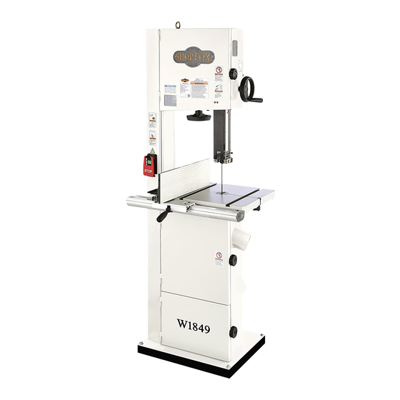
Page 7: Identification
Model W1849 (For Machines Mfd. Since 11/16) Identification Become familiar with the names and locations of the controls and features shown below to better understand the instructions in this manual. Upper Blade Tracking Blade Wheel Window Tension Cover Quick- Guide Post... -
Page 8: Controls & Components
Model W1849 (For Machines Mfd. Since 11/16) Controls.&.Components Refer to Figures 1–8 and the following descriptions to become familiar with the basic controls and components of this machine. Understanding these items and how they work will help you understand the rest of the manual and stay safe when operating this machine. - Page 9 Model W1849 (For Machines Mfd. Since 11/16) Guide.Post Blade.Tension.&.Tracking Figure 5. Blade tension scale, blade tension handwheel, and tracking window. Figure 3. Guide post controls. M. Blade Tension Scale: Displays blade tension using numbers 1–8. For reference purposes H. Guide Post Handwheel: Adjusts height of only—after you have found the proper...
- Page 10 Model W1849 (For Machines Mfd. Since 11/16) Table.Tilt Lower.Wheel.Adjustment Figure 7. Table tilt controls. Figure 8. Lower wheel adjustment controls. Table Tilt Lock Lever: Secures table tilt position on trunnion. Must be loosened X. Lower Wheel Adjustment Hub: Adjusts before table tilt can be adjusted.
-
Page 11: Safety
Model W1849 (For Machines Mfd. Since 11/16) SAFETY SAFETY For.Your.Own.Safety, Read.Manual.Before.Operating.Machine The. purpose. of. safety. symbols. is. to. attract. your. attention. to. possible. hazardous. conditions.. This. manual.uses.a.series.of.symbols.and.signal.words.intended.to.convey.the.level.of.importance.of.the. safety.messages..The.progression.of.symbols.is.described.below..Remember.that.safety.messages.by. themselves. do. not. eliminate. danger. and. are. not. a. substitute. for. proper. accident. prevention. mea- sures—this.responsibility.is.ultimately.up.to.the.operator! - Page 12 Model W1849 (For Machines Mfd. Since 11/16) WEARING.PROPER.APPAREL..Do not wear FORCING.MACHINERY..Do not force machine. It clothing, apparel, or jewelry that can become will do the job safer and better at the rate for entangled in moving parts. Always tie back which it was designed.
-
Page 13: Additional Safety For Bandsaws
Model W1849 (For Machines Mfd. Since 11/16) Additional.Safety.for.Bandsaws Serious cuts, amputation, or death can occur from contact with the moving saw blade during operation or if blade breakage occurs. To reduce this risk, anyone operating this machine MUST completely heed the hazards and warnings below. -
Page 14: Electrical
Model W1849 (For Machines Mfd. Since 11/16) ELECTRICAL Circuit.Requirements This machine must be connected to the correct size and type of power supply circuit, or fire or electrical damage may occur. Read through this section to determine if an The. machine. must. be. properly. set. up. -
Page 15: Grounding Requirements
Model W1849 (For Machines Mfd. Since 11/16) Grounding.Requirements This machine MUST be grounded. In the event of certain types of malfunctions or breakdowns, grounding provides a path of least resistance for electric current to travel—in The. machine. must. be. properly. set. up. -
Page 16: Converting Voltage To 220V
Plug 6-15 ............1 • Wire Cutters/Stripper........1 Ground To convert Model W1849 to 220V, do these steps: 1. DISCONNECT MACHINE FROM POWER! 2. Cut off existing 5-15 plug. Figure 11. Inside motor junction box. 3. Open motor junction box, then remove two wire nuts indicated in Figure 11. -
Page 17: Setup
Model W1849 (For Machines Mfd. Since 11/16) SETUP Unpacking This machine has been carefully packaged for safe This machine presents transportation. If you notice the machine has been serious injury hazards damaged during shipping, please contact your authorized to untrained users. Read Shop Fox dealer immediately. -
Page 18: Inventory
Model W1849 (For Machines Mfd. Since 11/16) Inventory The following is a list of items shipped with your machine. Before beginning setup, lay these items out and inventory them. Note: If you cannot find an item on this list, carefully check around/inside the machine and packaging materials. -
Page 19: Hardware Recognition Chart
Model W1849 (For Machines Mfd. Since 11/16) Hardware.Recognition.Chart USE THIS CHART TO IDENTIFY HARDWARE DURING THE INVENTORY/ASSEMBLY ⁄ " ⁄ " ⁄ " PROCESS. ⁄ " ⁄ " ⁄ " ⁄ " ⁄ " ⁄ " ⁄ " ⁄ "... -
Page 20: Cleaning Machine
Model W1849 (For Machines Mfd. Since 11/16) Cleaning.Machine To prevent corrosion during shipment and storage of your machine, the factory has coated the bare metal surfaces of your machine with a heavy-duty rust prevention compound. Gasoline.and.petroleum. products.have.low.flash. If you are unprepared or impatient, this compound can points.and.can.explode. -
Page 21: Machine Placement
Model W1849 (For Machines Mfd. Since 11/16) Machine.Placement Weight.Load Physical.Environment Refer to the Machine.Specifications for the The physical environment where your machine is weight of your machine. Make sure that the operated is important for safe operation and the surface upon which the machine is placed will longevity of its components. -
Page 22: Lifting & Moving
Model W1849 (For Machines Mfd. Since 11/16) Lifting.&.Moving Special care should be taken when moving this bandsaw. To reduce your risk of injury or accidental damage, use one of the following methods to lift or move this HEAVY LIFT! bandsaw. -
Page 23: Anchoring To Floor
Model W1849 (For Machines Mfd. Since 11/16) Anchoring.to.Floor Number of Mounting Holes ........4 Diameter of Mounting Hardware ......⁄ " Lag Screw Anchoring machinery to the floor prevents tipping or shifting and reduces vibration that may occur during operation, resulting in a machine that runs slightly quieter Flat Washer and feels more solid. -
Page 24: Assembly
Model W1849 (For Machines Mfd. Since 11/16) Assembly Before beginning the assembly process, refer to Items Needed for Setup and gather everything you need. " Ensure all parts have been properly cleaned of the heavy-duty rust-preventative applied at the factory, if applicable. - Page 25 Model W1849 (For Machines Mfd. Since 11/16) 6. Install table insert (see Figure 23). Table Insert 7. Install table gap screw lock lever, secure with (1) M8-1.25 thin hex nut and (1) 8 x 20mm flat washer (see Figure 23), then tighten gap screw to ensure table surface is flush across gap.
- Page 26 Model W1849 (For Machines Mfd. Since 11/16) 10. Thread (1) M8-1.25 hex nut onto lock lever, install Lock lock lever onto fence base, then tighten hex nut to Lever secure (see Figure 26). Fence Base Hex Nut M8-1.25 Figure 26. Fence base lock lever installed.
- Page 27 Model W1849 (For Machines Mfd. Since 11/16) 13. Mount fence to fence base guide, sliding T-channel around fence base guide plate (see Figure 29). — For normal workpieces or resawing, mount fence T-Channel in vertical position, as shown in Figure 29, then rotate fence base lock lever to secure.
-
Page 28: Dust Collection
Model W1849 (For Machines Mfd. Since 11/16) Dust.Collection Recommended CFM at Each Dust Port: ..400 CFM Do not confuse this CFM recommendation with the rating of the dust collector. To determine the CFM at the dust port, you must consider these variables: (1) CFM rating of... -
Page 29: Adjustment Overview
Model W1849 (For Machines Mfd. Since 11/16) Adjustment.Overview The bandsaw is one of the most versatile woodworking machines. However, it has multiple components that must be properly adjusted for the best cutting results. For practical and safety reasons, some adjustments and test operations must be performed before performing other necessary adjustments. - Page 30 Model W1849 (For Machines Mfd. Since 11/16) To adjust blade tracking, do these steps: 1. DISCONNECT MACHINE FROM POWER! 2. Adjust upper and lower blade guides away from blade, and raise upper guides approximately ⁄ Blade Tension the way up (refer to Adjusting "Euro-Style" Roller Quick-Release Disc Guides on Page 35 for detailed instructions).
-
Page 31: Test Run
Model W1849 (For Machines Mfd. Since 11/16) Test.Run Once assembly is complete, test run the machine to ensure it is properly connected to power and safety components are functioning properly. Serious. injury. or. death. can. result. from. using. this. machine. BEFORE. -
Page 32: Tensioning Blade
Model W1849 (For Machines Mfd. Since 11/16) Tensioning.Blade A properly tensioned blade is essential for making Blade accurate cuts, maximizing blade life, and making other Tension bandsaw adjustments. However, a properly tensioned Quick- blade will not compensate for cutting problems caused... - Page 33 Model W1849 (For Machines Mfd. Since 11/16) The.Deflection.Method The deflection method is much more subjective than Blade the flutter method. Each blade will deflect differently Tension and every user will determine what "moderate pressure" Quick- means. The following are general guidelines for tensioning Release the blade with this method.
-
Page 34: Fine-Tune Tracking
Model W1849 (For Machines Mfd. Since 11/16) Fine-Tune.Tracking During setup, the blade was tracked without the machine connected to power (refer to Page 27). In this procedure, the bandsaw is turned ON to perform fine-tuning of the tracking. Make small changes with the blade tracking knob as you monitor the effect on the blade tracking. -
Page 35: Adjusting Blade Support Bearings
Model W1849 (For Machines Mfd. Since 11/16) Adjusting.Blade.Support. Bearings The support bearings are positioned behind the blade near the blade guides and prevent the blade from pushing backward during cutting operations. Proper adjustment of the support bearings helps you make accurate cuts and... -
Page 36: Adjusting "Euro-Style" Roller-Disc Guides
Model W1849 (For Machines Mfd. Since 11/16) Adjusting."Euro-Style". Roller-Disc.Guides The "Euro-style" roller discs (see Figure 46) can be Roller Discs adjusted left to right, as well as front to back, relative to the blade. Properly adjusted roller discs provide side-to- side support, from just behind the gullets to the back of the blade, to help keep the blade straight while cutting. - Page 37 Model W1849 (For Machines Mfd. Since 11/16) 3. Loosen both roller-disc adjustment thumb screws Roller-Disc (see Figure 49), then position roller discs so they Adjustment are close to —but not quite touching—sides of blade. Thumb Screws Note: When the roller discs are properly adjusted,...
-
Page 38: Installing Blade Guide Roller Bearings
As an option to replace the standard "Euro-Style" roller- Cap Screws disc guides, Woodstock offers optional D4688 Blade Guide Roller Bearings specially designed to fit Model W1849 (see Accessories on Page 55). Installing these blade guides is relatively easy, though it requires first removing the blade and existing blade guide assemblies. -
Page 39: Adjusting Blade Guide Roller Bearings
Model W1849 (For Machines Mfd. Since 11/16) Adjusting.Blade.Guide. Roller.Bearings The optional blade guide roller bearings can be adjusted left-to-right, as well as front-to-back, relative to the blade. Properly adjusted blade guide bearings provide Whenever changing blade or adjusting side-to-side support, from just behind the gullets to the... - Page 40 Model W1849 (For Machines Mfd. Since 11/16) 3. Loosen both guide bearing adjustment cap screws Guide Bearing (see Figure 55), then position guide bearings so they Adjustment are close to —but not quite touching—sides of blade. Cap Screws Figure 55. Location of upper guide bearing adjustment cap screws (guide post cover removed for clarity).
-
Page 41: Aligning Table
Model W1849 (For Machines Mfd. Since 11/16) Aligning.Table To ensure cutting accuracy, the table should be aligned so that the miter slot is parallel to the bandsaw blade, and that the table is perpendicular (front to back) to the blade. These procedures work best with a wide ( ⁄... - Page 42 Model W1849 (For Machines Mfd. Since 11/16) Adjusting.Table.Perpendicular.to.Blade 1. DISCONNECT MACHINE FROM POWER! 2. Place a square on table and against back of blade, as illustrated in Figure 60. Table should be perpendicular to back of blade. Blade Square — If the table is perpendicular to the back of the blade, no adjustment is necessary;...
-
Page 43: Aligning Fence
Model W1849 (For Machines Mfd. Since 11/16) 5. Adjust positive stop bolt against bottom of table and secure it by tightening hex nut against trunnion bracket. 6. Check adjustment for accuracy once you have Blade tightened hex nut. 7. Loosen screw on pointer, but do not remove it. -
Page 44: Operations
Model W1849 (For Machines Mfd. Since 11/16) OPERATIONS General This machine will perform many types of operations that are beyond the scope of this manual. Many of these operations can be dangerous or deadly if performed incorrectly. The instructions in this section are written with the understanding that the operator has the necessary knowledge and skills to operate this machine. -
Page 45: Workpiece Inspection
Model W1849 (For Machines Mfd. Since 11/16) Workpiece.Inspection Basic.Functions.of.a.Bandsaw. A properly adjusted bandsaw can be safer to Some workpieces are not safe to cut or may operate than most other saws and performs require modification before they can be made many types of cuts with ease and accuracy. -
Page 46: Setting Upper Blade Guide Height
Model W1849 (For Machines Mfd. Since 11/16) Setting.Upper.Blade. Guide.Height When cutting, the blade guides must always be positioned so they just clear (no more than ⁄ ") the workpiece. The Guide Post guide post, shown in Figure 64, allows the upper blade... - Page 47 Model W1849 (For Machines Mfd. Since 11/16) Blade.Dimensions " Length Range ........120"–120 ⁄ " Width Range ..........⁄ "– ⁄ " Blade.Length " Measured by the blade circumference, blade lengths are specific to each bandsaw. They are determined by the wheel diameter and distance between the wheels.
- Page 48 Model W1849 (For Machines Mfd. Since 11/16) Tooth.Style Figure 67 illustrates the three main blade tooth styles: • Raker: Considered to be the standard because the tooth size and shape are the same as the tooth Raker Skip Hook gullet. The teeth on raker blades usually are very numerous, have no angle, and produce cuts by scraping the material.
- Page 49 Model W1849 (For Machines Mfd. Since 11/16) Blade.Material Bandsaw blades must meet two requirements: flexibility and hardness. The flexibility of a blade allows it to travel on the wheel as a band, while hardness allows the teeth to cut and hold an edge. Modern materials technology has...
-
Page 50: Blade Selection Chart
Model W1849 (For Machines Mfd. Since 11/16) Blade.Selection.Chart Use the blade selection chart below as a general guide when selecting a blade for your operation. Blade Width Cutting Operation NaNarrow ( ⁄ " — ⁄ ") MMedium ( ⁄ "—... -
Page 51: Blade Care & Break-In
Model W1849 (For Machines Mfd. Since 11/16) Blade.Care.&.Break-In Blade.Breakage Blade.Care Many conditions may cause a bandsaw blade to break. Blade breakage is unavoidable in A bandsaw blade is a thin piece of steel that is some cases, since it is the natural result of subjected to tremendous strain. -
Page 52: Changing Blade
Model W1849 (For Machines Mfd. Since 11/16) Changing.Blade Blade changes entail removing the existing blade, installing the new blade, then properly adjusting the blade tension, tracking, and guides. Disconnect bandsaw from power BEFORE changing blade. Serious Removing.Blade personal injury could occur if machine is started during this procedure. -
Page 53: Tilting Table
Model W1849 (For Machines Mfd. Since 11/16) Tilting.Table The table can be tilted from 5° left–45° right to make Positive beveled cuts. A table tilt scale with pointer is provided Trunnion Table Tilt Stop on the trunnion, and a hex bolt serves as a positive stop Adjustment for quickly returning the table back to 0°... -
Page 54: Ripping
Model W1849 (For Machines Mfd. Since 11/16) Ripping "Ripping" means cutting with the grain of the wood stock. For plywood and other processed wood, ripping simply means cutting down the length of the workpiece. Beveled ALWAYS use a push stick when ripping rip cuts may be performed by tilting the table. -
Page 55: Resawing
Model W1849 (For Machines Mfd. Since 11/16) Resawing "Resawing" means cutting the thickness of a board into two or more thinner boards (see Figure 77 for an example). The maximum height of a board that can be When resawing thin pieces, a wandering... -
Page 56: Stacked Cuts
Model W1849 (For Machines Mfd. Since 11/16) Stacked.Cuts One of the benefits of a bandsaw is its ability to cut multiple copies of a particular shape by stacking a number of workpieces together. However, before making stacked cuts, ensure that the table is perpendicular (90°) to the blade—otherwise, any error in this setting will be... -
Page 57: Accessories
Model W1849 (For Machines Mfd. Since 11/16) ACCESSORIES Bandsaw.Accessories The following bandsaw accessories may be available through your local Woodstock International Inc. Dealer. If you do not have a dealer in your area, these products are also available through online dealers. - Page 58 The D2057A Super Heavy-Duty Mobile Base supports your bandsaw so you can move it easily and lock it in place. Designed for long term and frequent moving of heavy machinery. All Shop Fox Adjustable Mobile Bases are strong enough to move heavy machines up to 700 lbs.
-
Page 59: Maintenance
Model W1849 (For Machines Mfd. Since 11/16) MAINTENANCE Schedule For optimum performance from your machine, follow this maintenance schedule and refer to any specific instructions given in this section. Daily • Tighten loose mounting bolts. • Check/replace worn or damaged saw blade. -
Page 60: Lubrication
Model W1849 (For Machines Mfd. Since 11/16) Lubrication An essential part of lubrication is cleaning the components before lubricating them. This step is critical because dust and chips build up on lubricated components, which makes them hard to move. Simply adding more grease to built-up grime will not result in smooth moving parts. - Page 61 Model W1849 (For Machines Mfd. Since 11/16) Blade.Tension.Adjustment.Assembly Look Through Here Lubrication Type ....GL2 Grease or Equivalent Amount ..........Thin Coat Frequency ..........As Needed To lubricate tension adjustment assembly, do these steps: 1. DISCONNECT MACHINE FROM POWER! Figure 81. Location of blade tension 2.
-
Page 62: Service
Model W1849 (For Machines Mfd. Since 11/16) SERVICE Troubleshooting The following troubleshooting tables cover common problems that may occur with this machine. If you need replacement parts or additional troubleshooting help, contact our Technical Support. Note: Before contacting Tech Support, find the machine serial number and manufacture date, and if available, your original purchase receipt. - Page 63 Model W1849 (For Machines Mfd. Since 11/16) Operating.Machine PROBLEM POSSIBLE CAUSE CORRECTIVE ACTION 1. Adjust blade tension (Page 30). Blade or teeth 1. Blade tension is incorrect. 2. Use correct blade for application (Page 44). break/crack. 2. Blade is incorrect for application.
- Page 64 Model W1849 (For Machines Mfd. Since 11/16) Operating.Machine.(Continued) PROBLEM POSSIBLE CAUSE CORRECTIVE ACTION Cut is crooked or 1. Excessive feed rate/pressure. 1. Reduce feed rate/pressure. 2. Increase blade tension (Page 30). blade wanders 2. Blade tension too loose. (blade lead).
-
Page 65: Tensioning/Replacing V-Belt
Model W1849 (For Machines Mfd. Since 11/16) Tensioning/Replacing. V-Belt To ensure optimum power transmission from the motor to the blade, the V-belt must be properly tensioned, and free of cracks, fraying, and wear. Belt tension and condition should be checked at least every 3 months—... - Page 66 Model W1849 (For Machines Mfd. Since 11/16) Replacing.V-Belt To replace the V-belt, you must remove the blade and Wheel Mount the lower wheel. After re-installation, you must properly Cap Screw & re-tension the V-belt. Washer Tools Needed: Hex Wrench 6mm ..........1 Hex Wrench 8mm ..........1...
-
Page 67: Blade Lead
Model W1849 (For Machines Mfd. Since 11/16) Blade.Lead Bandsaw blades may wander off of the layout line when sawing, as shown in Figure 88. This is called blade lead. Blade lead is usually caused by excessive feed rate/ pressure, a dull or abused blade, or improper blade Blade tension. -
Page 68: Adjusting Wheel Brushes
Model W1849 (For Machines Mfd. Since 11/16) Adjusting.Wheel.Brushes The lower wheel has brushes (see Figure 90) that are Hex Bolts designed to sweep sawdust off the wheel and blade during operation. In order to work properly, the brushes must make firm contact with the wheel. -
Page 69: Adjusting Guide Post Parallelism
Model W1849 (For Machines Mfd. Since 11/16) Adjusting.Guide.Post. Parallelism The guide post assembly should remain parallel with the blade front to back and side to side along its length of travel. If it does not, follow these instructions to adjust... - Page 70 Model W1849 (For Machines Mfd. Since 11/16) Checking/Adjusting. Guide. Post. Parallel. with. Blade.Front-to-Back 1. DISCONNECT MACHINE FROM POWER! Cap Screws and Flat Washers 2. Loosen guide post lock knob, lower blade guide assembly all the way, then tighten lock knob.
- Page 71 Model W1849 (For Machines Mfd. Since 11/16) 6. Loosen four cap screws shown in Figure 97. Cap Screws (1 of 4) Upper — If guide post to blade distance is greater at Set Screws bottom than at top, tighten two upper set screws...
-
Page 72: Aligning Wheels
Model W1849 (For Machines Mfd. Since 11/16) Aligning.Wheels The following adjustment was performed at the factory and should not need to be performed again unless there is a wheel alignment problem, or one or more wheels are replaced. When wheels are coplanar (see Figure 98), the bandsaw is more likely to cut straight without wandering;... - Page 73 Model W1849 (For Machines Mfd. Since 11/16) 4. Place coplanarity gauge up against both wheels in Coplanarity Gauge Gauge Positions positions shown in Figure 100. Make sure gauge fully extends across rims of both wheels. Tracking Knob Wheels Adjustment Figure 100. Illustration of using coplanarity gauge to check wheel alignment.
- Page 74 Model W1849 (For Machines Mfd. Since 11/16) Shimming.a.Wheel When the wheels are parallel but not coplanar, one of the wheels must be shimmed out to bring it into the same plane as the other wheel. Tip: Standard washers work well for shimming the wheel because they can easily be stacked to get the desired height.
- Page 75 Model W1849 (For Machines Mfd. Since 11/16) Adjusting.Lower.Wheel.Shaft.Position Lower Wheel If the lower wheel is tilted in relation to the upper wheel, Adjustment Hub perform the following procedure to make it coplanar with the upper wheel. There are four adjustment bolts with hex nuts in the lower wheel adjustment hub, shown in Figure 103.
-
Page 76: Calibrating Table Tilt Scale Pointer
Model W1849 (For Machines Mfd. Since 11/16) Calibrating.Table.Tilt. Scale.Pointer The table tilt scale pointer (see Figure 105) was calibrated at the factory. However, after prolonged use the pointer may shift, requiring adjustment. Table Tilt Scale Note: The table tilt scale functions as a basic guide only. -
Page 77: Electrical Safety Instructions
Model W1849 (For Machines Mfd. Since 11/16) Electrical.Safety.Instructions These pages are current at the time of printing. However, in the spirit of improvement, we may make changes to the electrical systems of future machines. Compare the manufacture date of your machine to the one stated in this manual, and study this section carefully. -
Page 78: Wiring Diagram
Model W1849 (For Machines Mfd. Since 11/16) Wiring.Diagram Read WARNING! Page 75 STOP ON/OFF Switch (viewed from behind) UNEXPECTED INJURY ˚ Before Wiring ON/OFF Switch HAZARD! KEDU HY56 Disconnect machine from power before changing cutting tools or perform- ing maintenance. -
Page 79: Parts
Model W1849 (For Machines Mfd. Since 11/16) PARTS Main 19-3 19-1 19-4 19-2 19-5 27-6 27-3 27-4 27-1 82-1 82-3 82-5 27-2 27-7 27-5 82-2 82-6 82-4 27-8 82-8 82-7 82-10 82-9 82-11 -77-... -
Page 80: Main Parts List
Model W1849 (For Machines Mfd. Since 11/16) Main.Parts.List REF PART # DESCRIPTION REF PART # DESCRIPTION XP1849001 DOOR SEAL 10 X 760 X 1MM X1849044 CAP SCREW M8-1.25 X 16 X1849002 CAP SCREW M6-1 X 20 X1849045 FENDER WASHER 8MM... -
Page 81: Table, Trunnion, & Blade Guides
Model W1849 (For Machines Mfd. Since 11/16) Table,.Trunnion,.&.Blade.Guides 96-9 96-10 96-12 96-11 96-4 96-5 114-18 114-19 114-17 114-24 114-25 96-1 96-8 114-20 96-13 114-16 96-2 96-7 114-15 114-21 114-14 96-5 96-3 96-6 114-13 96-12 114-12 96-1 114-23 114-11 114-22 114-10... -
Page 82: Table, Trunnion, & Blade Guides Parts List
Model W1849 (For Machines Mfd. Since 11/16) Table,.Trunnion,.&.Blade.Guides.Parts.List REF PART # DESCRIPTION PART # DESCRIPTION X1849051 MAGNET STRIP 7 X 340MM 99-2 X1849099-2 FLAT WASHER 6MM X1849052 GUARD CLEAR WINDOW 52 X 47 X 3MM 99-3 X1849099-3 CAP SCREW M6-1 X 8 X1849053 SET SCREW M4-.7 X 4... -
Page 83: Fence
Model W1849 (For Machines Mfd. Since 11/16) Fence 102-28 102-18 102-10 102-12 102-7 102-16 102-8 102-27 102-11 102-6 102-4 102-3 102-2 102-15 102-21 102-26 102-5 102-1 102-22 102-13 102-25 102-24 102-9 102-17 102-20 PART # DESCRIPTION PART # DESCRIPTION X1849102... -
Page 84: Labels & Cosmetics
Model W1849 (For Machines Mfd. Since 11/16) Labels.&.Cosmetics MODEL W1849 14" RESAW BANDSAW MODEL W1849 Specifications 14" RESAW BANDSAW Motor: 2 HP, 110V/220V, 1-Ph, 60 Hz To reduce risk of serious injury when using this machine: 1. Read and understand owner’s manual before operating. - Page 85 Model W1849 (For Machines Mfd. Since 11/16)
- Page 86 Fold along dotted lIne place stamp Here Woodstock international inc. p.o. box 2309 bellingham, Wa 98227-2309 Fold along dotted lIne tape along edges--please do not staple...
-
Page 87: Warranty
Woodstock International, Inc. will repair, replace, or arrange for a dealer refund, at its expense and option, the Shop Fox machine or machine part proven to be defective for its designed and intended use, provided that the original owner returns the product prepaid to an authorized warranty or repair facility as designated by our Bellingham, Washington office with proof of their purchase of the product within two years, and provides Woodstock International, Inc. - Page 88 High Quality Machines and Tools Woodstock International, Inc. carries thousands of products designed to meet the needs of today's woodworkers and metalworkers. Ask your dealer about these fine products:...
Need help?
Do you have a question about the W1849 and is the answer not in the manual?
Questions and answers