Advertisement
Quick Links
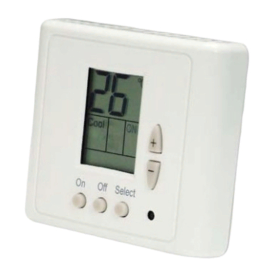
SUPER-SI THERMOSTAT
User manual
Installation and Operation Instructions
Contents
1. Installation Instruccions
2. Wiring connections
3. Micro Switch DIP Adjustments
4. Operation Manual
4.1Switch on / Switch off
4.2 Temperatures adjustment
4.3 System modes
4.4 Fan / autofan ventilation
4.5 Blocking / unblocking of thermostat buttons
1. Installation Instructions
- Separate the front panel of the back panel pressing the tab located at the top of the
unit.
- Remove the back panel.
- Align the back panel on the wall or a plain surface. Install 3 necessary screws
- Realize electrical connections as shown in electrical wiring diagram (attached on
the next page).
o
C
- Install the back panel's cover; first of all two clips on the bottom and then the
S
ET
Cool
ON
Heat
OFF
upper tap. Push until it would be fixed on the wall.
On/Off Mode
Fan
05.13 Ref. 201067 Rev. 101
Page
1
2
2
3
3
3
4
4
4
1
Advertisement

Subscribe to Our Youtube Channel
Related Manuals for meitav-tec SUPER-SI Series


Summary of Contents for meitav-tec SUPER-SI Series
-
Page 1: Installation Instructions
SUPER-SI THERMOSTAT User manual Installation and Operation Instructions Contents Page 1. Installation Instruccions 2. Wiring connections 3. Micro Switch DIP Adjustments 4. Operation Manual 4.1Switch on / Switch off 4.2 Temperatures adjustment 4.3 System modes 4.4 Fan / autofan ventilation 4.5 Blocking / unblocking of thermostat buttons 1. - Page 2 connections Wiring COMPRESSOR 1 COMPRESSOR 2 EXTERNAL SENSOR ELECTRIC RESISTANCE 2 PHASE WINDOW CONTACT ELECTRIC RESISTANCE 1 PHASE ELECTRIC RESISTANCE 3 PHASE HEAT PUMP – 4 WAY VALVE ORDINARY (supply) LINE (supply) 3. Micro Switch DIP Adjustments DEFAULT Important: SET MICRO SWITCH WITHOUT SUPPLY ENERGY IN THE THERMOSTAT HEAT PUMP (models to 501 included) HEAT PUMP (models 701 and superiors) ONLY COOL (WITH ELECTRIC RESISTANCE)
-
Page 3: Temperature Adjustment
SWITCH S1 Compressor temporization Fan in Saving Mode Modes Window contact FAN . Wthout Heat Pump or Change to FAN. 4 Min. ALWAYS delay Only cool Cooling with Off System economy AUTO delay (test) heating stage mode S1.1 S1.2 S1.3 S1.4 UNUSED S1.5... -
Page 4: System Modes
4.3 System modes Press the button MODE (Select) un time. Use the buttons “+” o “-“ to change in modes: • Cooling – Display “Cool” on the screen. Heating – Display “Heat” on the screen. Automatic change – Will display both words “Cool” and “Heat” on the screen and flicking the current active mode.
Need help?
Do you have a question about the SUPER-SI Series and is the answer not in the manual?
Questions and answers