Table of Contents
Advertisement
Quick Links
Download this manual
See also:
Instruction Manual
50 - 80 c.c. gasoline engine
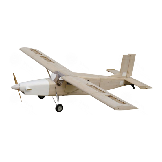
Requires : 5-channel radio w/ 8 high torque servos
Wing Span
Wing Area
Flying Weight
Fuselage Length
Warning! This model is not a toy.
It is designed for maximum performance. Please seek advice if one is not familiar with this kind
of engine powered precision model. Operating this model without prior preparation may cause
injuries. Remember, safety is the most important thing. Always keep this instruction manual at
hand for quick reference.
The World Models
Manufacturing Co., Ltd.
www.theworldmodels.com
A334PO31661701
Specifications
125 in / 3175 mm
2009 sq in / 130 sq dm
29.5 Ibs / 13400 g
90.5 in / 2300 mm
*Specifications are subject to change without notice.*
INSTRUCTION MANUAL
FACTORY PRE-FABRICATED
ALMOST-READY-TO-FLY(ARF)SERIES
MADE IN CHINA
( A334 )
Advertisement
Table of Contents

Related Manuals for The World Models Manufacturing PILATUS PC-6 PORTER


Summary of Contents for The World Models Manufacturing PILATUS PC-6 PORTER
- Page 1 INSTRUCTION MANUAL ( A334 ) 50 - 80 c.c. gasoline engine Requires : 5-channel radio w/ 8 high torque servos Specifications Wing Span 125 in / 3175 mm Wing Area 2009 sq in / 130 sq dm Flying Weight 29.5 Ibs / 13400 g Fuselage Length 90.5 in / 2300 mm *Specifications are subject to change without notice.*...
-
Page 2: Before You Begin
INDEX BEFORE YOU BEGIN PARTS LIST ASSEMBLY P.3-P.13 SAFETY PRECAUTIONS P.14 BEFORE YOU BEGIN Read through the manual before you begin, so you will have an overall idea of what to do. Check all parts. If you find any defective or missing parts contact your local dealer. Please DRY FIT and check for defects for all parts that will require CA or Epoxy for final assembly. -
Page 3: Parts List
Parts List 1. DECALS: A334 DEC -- set PLYWOOD 3x118.2x144mm -- 1 pc. MAIN WING -- 1 pair WOOD 10x10x150mm -- 1 pc. FUSELAGE -- 1 pc. TAIL PIECE -- 1 pc. FUEL TANK 800cc -- 1 set CABLE TIE (For Fuel Tank ) 1.5x8x500mm -- 1 pc. SCREW PA3x20mm -- 5 pcs WASHER d3.2xD10mm -- 5 pcs COVERING 30x600mm -- 2 pcs... - Page 4 Decals Screw PA3x20mm d3.2xD10mm Washer Cut out decal sheet, peel off backing sheet and apply on fuselage and wings. Decal Main Wings Bottom View Servo Lead d3.2xD10mm Washer Covering PA3x20mm Fuselage Left View Right View Instrument Panel A334PO31661701...
- Page 5 Stabilizer & Elevator Pushrod M4x55mm Socket Head Screw PM3x40mm Screw PWA2.3x8mm Screw PM3x40mm Washer d3.2xD10mm Nylon Insert Lock Nut d3.2xD10mm Washer Pre-glued The hinges are factory glued. M2x8mm Socket Head Screw PL4120300 1.5mm M2 Nut PWA2.3x8mm Completed M2 Nylon Insert Lock Nut Heavy Duty Clevis...
- Page 6 Vertical Fin & Rudder Pushrod M4x55mm Socket Head Screw PWA2x8mm Screw Pre-glued Nylon Insert Lock Nut B=B' M2x8mm Socket Head Screw PL4120300 Wire 1.5mm M2 Nut PWA2x8mm M2 Nylon Insert Lock Nut Heavy Duty Clevis M2 x 10mm The hinges are factory glued. Pushrod Remove coverings for all surfaces in contact before applying A/B epoxy glue.
- Page 7 Tail Landing Gear PWA2x8mm Screw Collar 3.1 mm Bottom View PWA2x8mm 3.1mm Collar Steering Arm M3x3mm Set Screw M2x8mm Heavy Duty Clevis M3x3mm Set Screw M2 Nut Wire Bottom View Copper Tube d2.5xD3.2x8mm Eye Screw M2.5x8x25mm Rudder pushwire Ø 1x150mm PA3.5x16mm Spring Bottom View...
-
Page 8: Main Landing Gear
Main Landing Gear M3x20mm Socket Head Screw PA3x30mm Screw PA3x20mm Screw Aluminum Plate PA1.7x8mm Screw Wheel Ø128mm 5.1mm Collar PA3x30mm 5.1 mm Collar 5.1mm Collar 6.1 mm Collar Mounting Plate M3x20mm M3x3mm M3x3mm PA3x20mm d6xD15mm Washer Set Screw Set Screw Aluminum Plate Landing Gear Washer d3.2xD10mm... -
Page 9: Fuel Tank
Fuel Tank Cable Tie 1.5x8x500mm Radio Equipment Plywood 3x191.4x247.9mm Set Screw 3x3mm Linkage Connector Washer 3x3mm Set Screw Throttle Pushwire Washer Washer 1.5mm Throttle Pushrod 1.8x700mm Battery Receiver M2 Nut Ø Sponge Throttle Servo Throttle Servo 10x80x200mm Switch Please refer to the attached sheet for linkage connector installation. - Page 10 Windows & Pilot Plastic Plate Pilot Screw PM3x35mm d3xD7mm Washer Nylon Insert Lock Nut Door handle Seting Door M3 Nylon Insert Lock PM3x35mm Washer Washer d3xD7mm d3xD7mm Securely glue the windows to the fuselage. Please refer to the attached sheet for usage of the transparent 3D template. Cowling First insert the grommet to the cowling then apply screw.
- Page 11 Aileron Servo & Pushrod M4x60mm Socket Head Screw Servo wire PWA2.3x8mm Screw Nylon Insert Lock Nut M2x8mm Socket Head Screw PL4120300 Pre-glued M2 Nut The hinges are factory glued. Bottom View Left Wing Pushrod w/ Threads(For Aileron) M3x116mm Pushrod w/ Threads(For Flap) M3x96mm 1.5mm PWA2.3x8mm...
- Page 12 Main Wing Wing Tube Ø25.4x1110mm Wire Ø0.8mm Set Screw Lead to Aileron Servo Wing Tube Ø22x1100mm Completed Self Tightening Set Screw M3X8mm Wing Latch Wing Tube Completed Wing Struts Screw HM4x15mm Nylon Insert Lock Nut d4.5xD9mm Washer Washer d3xD7mm HM4x15mm HM4x15mm HM4x12mm d4.5xD9mm...
- Page 13 Wing Setting A=A` B=B` C=C` A334PO31661701 P.12...
-
Page 14: Control Throws
Control Throws Adjust the control throws as shown in the diagram. These throws are good for general flying. You can adjust according to your personal preference. Flaps (near fuselage) Rudder 40mm 40mm 50mm Ailerons (away from fuselage) Elevator 25mm 20mm 25mm 20mm C.G. -
Page 15: Important Safety Precautions
Warning! Important Safety Precautions # First time flyer should never fly by himself / herself. Assistance from experienced flyer is absolutely necessary. # Pre-flight adjustment must be done before flying, it is very dangerous to fly a badly pre-adjusted aircraft. is specially designed to be powered by 50c.c. - Page 16 LINKAGE CONNECTOR HW7111050 & HW7111060 Drill 2mm hole at servo horn. Insert linkage connector into servo horn. Make sure shoulder of screw is cleared from servo horn. Add washer to reduce play if necessary. Shoulder Tighten up the round nut against the shoulder.
- Page 17 Usage of the transparent 3D template This transparent 3D template is used for position guidance of the actual cutting of the pre-painted cowling. Simply cut the transparent 3D template to fit your engine and exhaust pipe, then slide onto the actual cowling and use as template to mark the openings required for final cutting.
-
Page 18: Optional Parts
Optional Parts ACCESSORIES) Clevis Wrench 180mm Extension Code No. Size Package Code No. Size Package PL8210010 1 set KW0011800 180mm 1 set Large Clevis Small Clevis Special tool for clevis installation. Suitable for standard and small (EP) clevis. 180mm Y-Cord Code No. - Page 19 A334PO31661701...
- Page 20 A334PO31661701...
Need help?
Do you have a question about the PILATUS PC-6 PORTER and is the answer not in the manual?
Questions and answers