Table of Contents
Advertisement
Quick Links
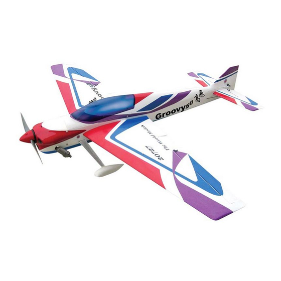
0.52-0.70 cu.in. displacement 4-stroke
R
equire : -channel
Wing Span
Wing Area
Flying Weight
Fuselage Length
Warning !This model is not a toy.
It is designed for maximum performance. Please seek advice if one is not familiar with this kind
of engine powered precision model. Operating this model without prior preparation may cause
injuries. Remember, safety is the most important thing. Always keep this instruction manual at
hand for quick reference.
s 4
* Specifications are subject to change without notice.*
radiow/5standardservos
Specifications
53.5 in / 1360 mm
536 sq in / 34.6sq dm
5.2 lbs / 2350 g
53.5 in / 1360 mm
INSTRUCTION MANUAL
FACTORY PRE-FABRICATED
ALMOST-READY-TO-FLY (ARF) SERIES
MADE IN CHINA
Advertisement
Table of Contents

Subscribe to Our Youtube Channel
Related Manuals for The World Models Manufacturing GROOVY 3A 50


Summary of Contents for The World Models Manufacturing GROOVY 3A 50
- Page 1 INSTRUCTION MANUAL 0.52-0.70 cu.in. displacement 4-stroke equire : -channel radiow/5standardservos Specifications 53.5 in / 1360 mm Wing Span Wing Area 536 sq in / 34.6sq dm Flying Weight 5.2 lbs / 2350 g Fuselage Length 53.5 in / 1360 mm * Specifications are subject to change without notice.* Warning !This model is not a toy.
-
Page 2: Before You Begin
I N D E X BEFORE YOU BEGIN P. 1 PARTS LIST P. 2 ASSEMBLY P.3-P.10 SAFETY PRECAUTIONS P. 10 BEFORE YOU BEGIN Read through the manual before you begin, so you will have an overall idea of what to do. Check all parts. -
Page 3: Parts List
Parts List 1. MAIN WING -- 1 pair 9. ENGINE MOUNT PL5111050 -- 1 set SOCKET HEAD SCREW M4x22mm -- 4 pcs 2. SCREW PB2x22mm -- 6 pcs WASHER d4xD9mm -- 4 pcs FUEL TUBE Ø6x5mm -- 4 pcs 10. FUEL TANK 320cc -- 1 set CLEVIS -- 2 pcs BALSA 8x8x89mm (For Fuel Tank Position Fixing) -- 1 pc. -
Page 4: Aileron Servo
Main Wing Aileron Servo Lead A p p l y i n s t a n t t y p e C A g l u e t o b o t h s i d e s o f e a c h h i n g e . -
Page 5: Tail Landing Gear
Vertical Fin & Rudder Apply instant type CA glue to both sides of each hinge. A = A' Tail Landing Gear Screw PA3 x 12mm PA3 x 12mm Ø25mm 1.5mm 2.1mm Collar Collar 2.1mm 3 x 3mm Set Screw 2.1mm Bottom View Main Landing Gear M2.5 12mm SocketHeadScrew... -
Page 6: Rudder Pullwire
Rudder Pullwire Press down the center TWM PL8210010 1/3 portion CLEVIS WRENCH Screw PM2x25mm Ring Fuel Tube 6 x 5mm Wire Copper Tube Tri-horn Ø1mm pilot holes for World Models tri-horn are pre-drilled. M3 x14mm Please look for pin-hole marks at under side of control surfaces. Clevis Rigging Coupler 1.8 x 27mm... - Page 7 Fuel Tank Fuel Tank Fuel Tank 320cc Balsa 8 x 8 x 89mm Rubber Band (For Fuel Tank Position Fixing Rubber Band Fuel Tank 320cc Installed Balsa 8x8x89mm (For fuel tank Fuel Tank position fixing) 320cc Top View Bottom View Engine 115mm Screw...
-
Page 8: Radio Equipment
3x3mm Set Screw Servo Set Included with the radio Set. Set Screw 3 x 3mm Linkage Connector Washer Washer 2m m Throttle Servo. Washer Please refer to attached sheet for linkage connector installation. Install and arrange the servo as shown in the diagram. Radio Equipment Pushrod Ø1 8x112mm... - Page 9 Step 1. Insert the aluminum wing tube with the pre-drilled hole end into the right wing. Align Main Wing the lines marked at the wing root and wing tube, then apply the PM3 X 18mm machine screw through the pre-drilled hole on top of the wing. ( please confirm the alignment of the hole by putting a 2.5mm diameter rod through the pre-drilled wing hole before applying the screw ) The hole on the wing tube is pre-threaded, do not over tighten the PM3 screw, the set up is for Screw...
- Page 10 Canopy First insert the grommet to the canopy then apply screw. Screw PWA2.3x8mm Apply double-sided tape Screw HM3x16mm d1.5 x D6.5 mmSilicon Grommet PWA2.3 x 8mm Washer d3xD7mm d1.5 x D6.5 mm Silicon Grommet d3xD7mm Washer HM3x16mm Wing Setting Adjust the wing and fuselage configuration as shown in the diagrams. A = A ' B = B ' C = C '...
- Page 11 Adjust the control throws as shown in the diagram. These throws are good for general flying. You can adjust according to your personal preference. Elevator 18mm 18mm Rudder 45mm 45mm Ailerons 10mm 10mm The ideal C.G. position is 135mm (5.32 in.) behind the leading edge measured at where the wing meets the fuselage.
- Page 12 LINKAGE CONNECTOR HW7111050 & HW7111060 Drill 2mm hole at servo horn. Insert linkage connector into servo horn. Make sure shoulder of screw is cleared from servo horn. Add washer to reduce play if necessary. Shoulder Tighten up the round nut against the shoulder.
- Page 13 Product Registration Form (US Customers) We would like to share with you any relevant information regarding your model, including product news and free upgrade parts when applicable. Please fill in the following and send to AirBorne Models, 4749-K, Bennett Drive, Livermore, CA 94551 USA. 1.
- Page 14 180mm Extension Package Package Code No. Size Code No. Size Package Code No. Size Code No. Package Size Large Clevis Small Clevis Special tool for clevis installation. Suitable for standard and small Package Code No. Size (EP)clevis. KP0041300 Code No SV4031 Package Code No.
- Page 15 The World Models Manufacturing Co., LTD. www .thew orldm odels .com A189PO22440912...
Need help?
Do you have a question about the GROOVY 3A 50 and is the answer not in the manual?
Questions and answers