Table of Contents
Advertisement
Quick Links
0.40-0.46 cu.in. displacement 2-stroke
0.48
-0.56
R
equire : -channel
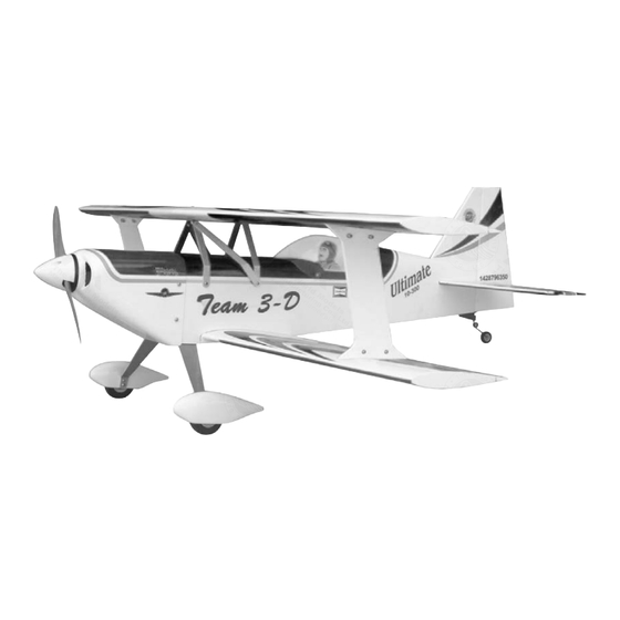
Wing Span
Wing Area
Flying Weight
Fuselage Length
Warning !This model is not a toy.
It is designed for maximum performance. Please seek advice if one is not familiar with this kind
of engine powered precision model. Operating this model without prior preparation may cause
injuries. Remember, safety is the most important thing. Always keep this instruction manual at
hand for quick reference.
A009SPO26741109
cu.in. displacement 4-stroke
s 4
and1miniservo
* Specifications are subject to change without notice.*
radiow/3standardservos
Specifications
42.0 in / 1060 mm
578 sq in / 37.3 sq dm
4.5 lbs / 2050 g
39.5 in / 1000 mm
INSTRUCTION MANUAL
FACTORY PRE-FABRICATED
ALMOST-READY-TO-FLY (ARF) SERIES
MADE IN CHINA
Advertisement
Table of Contents

Related Manuals for The World Models Manufacturing ULTIMATE - 40S


Summary of Contents for The World Models Manufacturing ULTIMATE - 40S
- Page 1 INSTRUCTION MANUAL 0.40-0.46 cu.in. displacement 2-stroke 0.48 -0.56 cu.in. displacement 4-stroke equire : -channel radiow/3standardservos and1miniservo Specifications Wing Span 42.0 in / 1060 mm Wing Area 578 sq in / 37.3 sq dm Flying Weight 4.5 lbs / 2050 g Fuselage Length 39.5 in / 1000 mm * Specifications are subject to change without notice.*...
-
Page 2: Before You Begin
I N D E X BEFORE YOU BEGIN P. 1 PARTS LIST P. 2 ASSEMBLY P. 3 -11 SAFETY PRECAUTIONS P.11 BEFORE YOU BEGIN Read through the manual before you begin, so you will have an overall idea of what to do. Check all parts. -
Page 3: Parts List
Parts List 1. MAIN WING (Lower) --1 pair THROTTLE PUSHWIRE Ø1.2x300mm -- 1 pc. PLASTIC TUBE d2xD3x200mm -- 1 set 2. PLYWOOD 5x28x48mm (For Aileron Servo) -- 1 pc. RING Ø2.3mm PL4112023 -- 2 pcs 15. PUSHROD CONECTOR 4x9x20mm PL4410010 -- 1 set PUSHROD Ø1.8x70mm (For Elevator Servo) -- 1 pc. -
Page 4: Aileron Servo
Main Wing (Lower) A p p l y i n s t a n t t y p e C A g l u e t o b o t h s i d e s o f e a c h h i n g e . CABANE MOUNT CABANE MOUNT Aileron Servo... -
Page 5: Stabilizer & Elevator
Main Wing (Upper) CABANE MOUNT CABANE MOUNT Bottom View Apply instant type CA glue to both sides of each hinge. Stabilizer & Elevator (Stabilizer) Temporary install the main wing, adjust leveling of the stabilizer to make it as Apply instant type CA glue to both sides parallel to the main wing as possible. -
Page 6: Tail Landing Gear
Tail Landing Gear Screw PA3x12mm Collar 2.1mm 2.1mm Collar PA3x12mm M3x3mm Set Screw Bottom View Ø1mm pilot holes for World Models tri-horn are pre-drilled. Elevator Pushrod Please look for pin-hole marks at under side of control surfaces. Screw PB2x12mm TWM PL8210010 CLEVIS WRENCH ≈46mm PB2x12mm... -
Page 7: Main Landing Gear
Main Landing Gear KA2.3x8mm Screw M3x3mm Set Screw Washer d4xD9mm Screw M3x16mm HM4x 35mm M3x16mm Screw HM4x35mm d2XD8mm Quick Release Nylon Rivet Collar Plate 1mm 4.1mm Washer d3xD7mm d3xD7mm Washer Washer d4xD9mm Collar 4.1mm Completed Bottom View Engine Mount M4x 25mm Socket Head Screw Engine Mount Washer PL5111050... - Page 8 Servo Set 3x3mm Set Screw 3x3mm Set Screw Linkage Connector Included with the radio Set. Washer Washer Washer 2m m Throttle Servo. Please refer to the attached sheet for linkage connector installation. Engine M3 Nut d3xD7mm Washer M3x25mm SocketHeadScrew Washer d3xD7mm d3xD7mm Washer...
-
Page 9: Radio Equipment
Radio Equipment Install and arrange the servo as shown in the diagram. J1(Pushrod Ø1.8x95) PLYWOOD Charge Receptacles Front BALSA KP0041300 3x100x103mm 5x5x97mm Elevator Servo Throttle Pushwire Ø1.2x280mm J2(Pushrod Ø1.8x440) Pushrod Connector Fuel Tube Ø6x5mm Sponge Elevator Pushrod Ø1.8x70mm M2 Nut Straper BALSA Rudder Pushrod... - Page 10 Main Wing (Lower) HM4x25mm Socket Head Screw Washer d4xD15mm Washer HM4x25mm d4xD15mm Bottom View d3xD7mm Main Wing M3x20mm M3x30mm Washer M3 Nylon d3xD7mm Please install in Insert Lock Nut Washer correct direction M3 Nylon PM2x8mm Screw Insert Lock Nut M3x30mm Socket Head Screw PM2x8mm M3x20mm...
- Page 11 Ø1mm pilot holes for World Models tri-horn are pre-drilled. Main Wing Please look for pin-hole marks at under side of control surfaces. Screw PB2x12mm Main Wing (Upper) Horn Clevis Pushrod Ø1.8x145mm Fuel Tube PB2x12mm Ø6x5mm Clevis Horn Main Wing (Lower) Wing Setting A=A' B=B' C=C' D=D' E=E' F=F' G=G'...
-
Page 12: Control Throws
Adjust the control throws as shown in the diagram. These throws are good for general flying. You can Control Throws adjust according to your personal preference. Elevator 10mm 10mm Rudder 30mm 30mm Ailerons The ideal C.G. position is 81mm (3 2 in.) behind the leading edge measured at top wing center line. - Page 13 LINKAGE CONNECTOR HW7111050 & HW7111060 Drill 2mm hole at servo horn. Insert linkage connector into servo horn. Make sure shoulder of screw is cleared from servo horn. Add washer to reduce play if necessary. Shoulder Tighten up the round nut against the shoulder.
- Page 14 Usage of the transparent 3D template This transparent 3D template is used for position guidance of the actual cutting of the pre-painted cowling. Simply cut the transparent 3D template to fit your engine and exhaust pipe, then slide onto the actual cowling and use as template to mark the openings required for final cutting.
- Page 15 180mm Extension Package Package Code No. Size Code No. Size Package Code No. Size Code No. Package Size Large Clevis Small Clevis Special tool for clevis installation. Suitable for standard and small Package Code No. Size (EP) clevis. KP0041300 Code No SV4031 Package Code No.
- Page 16 A009SPO26741109...
Need help?
Do you have a question about the ULTIMATE - 40S and is the answer not in the manual?
Questions and answers