Table of Contents
Advertisement
Quick Links
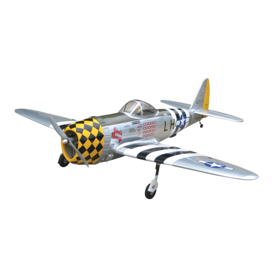
P-47D THUNDERBOLT
1.20 cu. in. displacement 4-stroke
Requires: 6-channel radio w/ 7 standard servos
and 2 low profile retract servos
Wing Span
Wing Area
Flying Weight
Fuselage Length
*Specifications are subject to change without notice.*
Warning! This model is not a toy.
It is designed for maximum performance. Please seek advice if one is not familiar with this
kind of engine powered precision model. Operating this model without prior preparation may
cause injuries. Remember, safety is the most important thing. Always keep this instruction
manual at hand for quick reference.
THE WORLD MODELS
MANUFACTURING CO., LTD.
FACTORY PRE-FABRICATED
ALMOST-READY-TO-FLY (ARF) SERIES
MADE IN CHINA
www.theworldmodels.com
Specifications
70 in / 1780 mm
893 sq in / 57.6 sq dm
10.7 Ibs / 4850 g
67 in / 1580 mm
INSTRUCTION MANUAL
Advertisement
Table of Contents

Related Manuals for The World Models Manufacturing P-47D THUNDERBOLT


Summary of Contents for The World Models Manufacturing P-47D THUNDERBOLT
-
Page 1: Specifications
INSTRUCTION MANUAL P-47D THUNDERBOLT 1.20 cu. in. displacement 4-stroke Requires: 6-channel radio w/ 7 standard servos and 2 low profile retract servos Specifications Wing Span 70 in / 1780 mm Wing Area 893 sq in / 57.6 sq dm Flying Weight 10.7 Ibs / 4850 g... -
Page 2: Before You Begin
P-47D THUNDERBOLT I N D E X BEFORE YOU BEGIN P. 1 P. 2 PARTS LIST P.3-P.12 ASSEMBLY SAFETY PRECAUTIONS P.13 BEFORE YOU BEGIN Read through the manual before you begin, so you will have an overall idea of what to do. -
Page 3: Parts List
Parts List 12. FUEL TANK 450cc -- 1 set 1. MAIN WING -- 1 pair BALSA 10x10x113mm (For Fuel Tank Position Fixing) -- 1 pc. 2. RETRACTABLE LANDING GEAR -- 1 pair 13. LINKAGE CONNECTOR 2.1mm -- 1 set MAIN WHEEL PL3112090 Ø90mm -- 2 pcs MAIN LANDING GEAR COVER -- 1 pair 14. -
Page 4: Retractable Landing Gear
Main Wing Pre-glued Aileron Servo Lead Flap Servo Lead Bottom View Retractable Landing Gear PM2x6mm Screw PM2x6mm M2 Nut M2 Nut d2xD5mm Washer d2xD5mm Washer Bottom View Please dry fit wing joiner into left and right wing to make sure they fit with the Main Wing proper dihedral angle, mark the wing joiner if necessary. - Page 5 Flap & Aileron Servo Fuel Tube PWA 2 x 12mm Straper 6x5mm Ø PM2x18mm Screw Ø1mm pilot holes for World Models tri-horn are pre-drilled. PM2x20mm Screw Please look for pin-hole marks PWA 2x12mm Screw at under side of control surfaces. 1.5mm Pushrod PM2x20mm...
- Page 6 Stabilizer & Elevator Pre-glued (Stabi l i zer) (Mai n Wi ng) B=B' A=A' Temporary install the main wing, adjust leveling of the stabilizer to make it as parallel to the main wing as possible Completed Vertical Fin & Rudder Pre-glued C=C' Completed...
-
Page 7: Elevator Pushrod
Tail Landing Gear PA3x12mm Screw PA3x12mm 1.5mm 2.6mm Collar 3mm Set Screw 3mm Set Screw Bottom View Elevator Pushrod Ø1m m pilot holes for Wor ld Models tr i-hor n ar e pr e-dr illed. Please look for pin-hole m ar ks at under side of contr ol sur faces. PM2x25mm Screw P M2 x2 5mm Elevator Pushrod... -
Page 8: Fuel Tank
Engine Mount Dowel Ø7.2x9mm M6x15mm Blind Nut M6x30mm Socket Head Screw d6xD15mm Washer d6xD15mm Washer Socket Head Screw M6x15mm Blind Nut M6x30mm Apply thread locker to screws Engine Mount Blind nuts are off-centered to keep PL5911120 the spinner at the fuselage axis. A: Inverted mount with Pitts type muffler. - Page 9 Servo Set 3x3mm Set Screw Linkage Connector Throttle Pushwire M2 Nut 2mm Washer 1.5mm Throttle Servo M2 Nut Please refer to the attached sheet for linkage connector installation. Engine Installed Engine Position M4x35mm Socket Head Screw 152mm 5.98in KM3x20mm Screw M4 Nylon Insert Lock Nut M3 Nylon Insert Lock Nut M4 Nylon Insert Lock Nut...
-
Page 10: Radio Equipment
Radio Equipment Install and arrange the servo as shown in the diagram. Elevator Pushrod Ø1.8x110mm J1(Pushrod Ø1.8x110mm) Pushrod Connector M2 Nut J2(Pushrod Ø1.8x935mm) Elevator Servo KM2x8mm Rudder Servo Fuel Tube Balsa Elevator Servo Ø6x5mm 8x8x61mm Straper Rudder Pushrod Ø1.8x1025mm Plywood Sponge 6x67x120mm Plastic Tube... - Page 11 Air Scoop & Exits Super Charger Exit Air Scoop Bottom View Super Charger Exit Intercooler Air Exit Intercooler Air Exit Bottom View Canopy First insert the grommet to the canopy then apply screw. PWA2.3x8mm Screw Pilot d1.5xD6.5mm Silicon Grommet Apply double-sided tape Silicom Grommet PWA2.3x8mm...
- Page 12 Please refer to the attached sheet for usage of the transparent 3D template. Cowling First insert the grommet to the cowling then apply screw. PWA2.6x12mm Screw d1.5xD6.5mm Silicon Grommet Oil Cooler Shutter PWA2.6x12mm Silicom Grommet d1.5xD6.5mm Spinner Nut Ø22mm Bottom View Wing Setting Adjust the wing and fuselage configuration as shown in the diagrams.
-
Page 13: Control Throws
Control Throws Adjust the control throws as shown in the diagram. These throws are good for general flying. You can adjust according to your personal preference. Elevator 18mm 18mm Rudder 25mm 25mm Flaps (near fuselage ) 35mm Ailerons ( away from fuselage ) 12mm 12mm C.G. -
Page 14: Landing Gear
Pre - flig h t ad ju stm en t m u st b e d o n e b efo re flyin g , it is very d an g ero u s to fly a b ad ly p re - ad ju sted aircraft. P-47D THUNDERBOLT is specially designed to be powered by 1.20 4-stroke glow engine, using a more powerful engine does not mean better performance. In fact, over powered engine may cause severe damage and injuries. - Page 15 LINKAGE CONNECTOR HW7111050 & HW7111060 Drill 2mm hole at servo horn. Insert linkage connector into servo horn. Make sure shoulder of screw is cleared from servo horn. Add washer to reduce play if necessary. Shoulder Tighten up the round nut against the shoulder.
- Page 16 Usage of the transparent 3D template This transparent 3D template is used for position guidance of the actual cutting of the pre-painted cowling. Simply cut the transparent 3D template to fit your engine and exhaust pipe, then slide onto the actual cowling and use as template to mark the openings required for final cutting.
- Page 17 http://www.theworldmodels.com A2130806...
Need help?
Do you have a question about the P-47D THUNDERBOLT and is the answer not in the manual?
Questions and answers