Advertisement
Quick Links
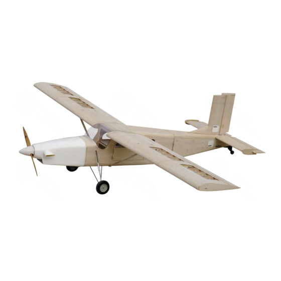
Wing Span
Wing Area
Flying Weight
Fuselage Length
Requires
Warning! This model is not a toy.
It is designed for maximum performance. Please seek advice if one is not familiar with this kind
of engine powered precision model. Operating this model without prior preparation may cause
injuries. Remember, safety is the most important thing. Always keep this instruction manual at
hand for quick reference.
The World Models
Manufacturing Co., Ltd.
www.theworldmodels.com
:
125 in / 3175 mm
:
2009 sq in / 130 sq dm
:
29.5 lbs / 13400 g
:
90.5 in / 2300 mm
:
5-channel radio w/8 high torque servos
50-80 c.c. gasoline engine
*Specifications are subject to change without notice.*
INSTRUCTION MANUAL
[ A334 Kit ]
[ A335 Kit ]
PRECISION LASER CUT
EASY BUILT KIT SERIES
MADE IN CHINA
Advertisement

Related Manuals for The World Models Manufacturing PILATUS PC-6 PORTER


Summary of Contents for The World Models Manufacturing PILATUS PC-6 PORTER
- Page 1 INSTRUCTION MANUAL [ A334 Kit ] [ A335 Kit ] Wing Span 125 in / 3175 mm Wing Area 2009 sq in / 130 sq dm Flying Weight 29.5 lbs / 13400 g Fuselage Length 90.5 in / 2300 mm Requires 5-channel radio w/8 high torque servos 50-80 c.c.
- Page 2 The World Models The World Models MAIN WING ASSEMBLY W15A Lay out parts for the wings. W16A 1. 1 Remove parts from plywood, cut connecting taps when required. 1.2 Cut open CA glue tip for CA application. Make sure open- Glue and join W15 to W15A, W16 to W16A.
- Page 3 The World Models The World Models W16B Glue W16B to W16/W16A to reinforce the joint. Note that W16B should flush with slot. Glue W21 between W4 and W5, W21 between W9 and W9. Make sure the half rib is facing inward and join to W21.
- Page 4 The World Models The World Models W13A W13B W13/W13A W14/W14A W14A Glue and join W14 and W14A. 1.10 Glue and join W13 and W13A. Glue W13B for joint rein- forcement. Make sure W13B flush with the adjacent slot. Glue W13/W13A to ribs, use tape to hold in place. W17B W17A W17/W17A...
- Page 5 The World Models The World Models W32A W20B 1.14 Glue and join W32 and W32A. Glue W32.W32A on bottom of wing from leading edge to spar. Flip over the wing and apply glue to all surfaces in contact between ribs and shee- ting W32/W32A.
- Page 6 The World Models The World Models W33A W33F W33E 1.18 Whe glue is cured, cut and remove rough edges with sand paper. W33G W33G W33C W33B W33D 1.17 1.19 Glue and join W33 and W33A, W33E and W33F. Apply Glue W12 and W33 in place. Remove rough edges with slow curing glue as white glue to the top of wing frame sand paper.
- Page 7 The World Models The World Models 1.23 Glue W25, W28, W29, W30 and W31 in place. Apply slow curing glue to all surfaces in contact with W34. 1.20 Lay out parts for flaps. W34A 1.24 Then glue W34 in place, add glue around W30. 1.25 Remove rough edges with sand paper then glue W26 1.21...
- Page 8 The World Models The World Models W29A 1.30 Glue W25, W29, W29A, W30 and W31. Apply slow curing glue to all surfaces in contact with W35. 1.27 Lay out parts for ailerons. W19A W35A 1.31 Then glue W35 in place. 1.32 Remove rough edges at both ends with san paper, the 1.28...
- Page 9 The World Models The World Models HORIZONTAL STABILIZER AND ELEVATOR ASSEMBLY Lay out parts for horizontal stabilizer and elevator Align S11 with slot on S8, and glue the narrower flat side 1.34 Insert hinges to aileron and flap, then install to left wing. of S11 to S8 as shown on figure B.
- Page 10 The World Models The World Models Glue S1/S10 to S8/S11, then glue S2, S3, S4 and S5. Note that the larger slot of each rib should be on the same side of the stabilizer. Insert S13 into round holes and apply glue. Glue S12 in place.
- Page 11 The World Models The World Models Copper Tube 2.10 Glue S15/S17 in place. Glue in S20, S21 and S22. Apply Align center of S8A with the 2 holes as shown on figure A glue to S18. When cured, apply slow curing glue to surfaces and glue in place.
- Page 12 The World Models The World Models VERTICAL STABILIZER AND RUDDER ASSEMBLY Lay out parts for the vertical fin and rudder 2.12 Use sand paper to remove rough edges. 2.13 Apply same procedures to assemble the other elevator. Insert V2, V3 and V4 to V8 grooves and glue in place. Make sure double slot side of ribs are facing up.
- Page 13 The World Models The World Models V13A Glue V7 and V7A in place. Glue V13 in place. Flip over frame and apply glue to all surfaces in contact. When cured apply slow curing glue to surfaces in contact with V13A, press V13A to frame and use rubber band to hold in place.
- Page 14 The World Models The World Models V12A Cut off and sand down rough edges. Glue V12 and V12A in place. Glue V11 in place. 3.10 Insert V9 and V18 into V14 slot and glue in place. A334KITPO31661705 P.13...
- Page 15 The World Models The World Models 3.11 Glue in V15, make sure slots align with ribs. 3.14 Glue in V27, apply glue to all surfaces in contact. When cured, apply slow curing glue to frame and glue in the other V27. 3.12 Glue in V17.
-
Page 16: Fuselage Assembly
The World Models The World Models Glue in F14 and F52, make sure all the latches are inside corresponding slots. 3.17 Install align-pro hinges. Do not apply glue at this stage. FUSELAGE ASSEMBLY Insert F13 and F72 into side panel.Apply glue when both F13 and F72 are in position. - Page 17 The World Models The World Models Put tail section upright and glue in F70. Make sure latches are fully inserted into slots when applying glue. F41C F42A F41C F41A F42A Glue in F41A, F41C and F42A. F71C F71D F56A F45B F45A F45A F46A F45B...
- Page 18 The World Models The World Models F27A Apply slow curing glue to frame. Apply moisture to outer 6 cm portion of F28 to make it more flexible and press onto tail section frame. Use tape to hold F28 in place. When cured apply glue to all surfaces in contact for reinforcement.
- Page 19 The World Models The World Models 4.13 Remove rough edges with knife and sand paper. 4.14 4.12 Glue in F49, F48, F54, F53, F50 and copper tube. Before Trial fit F71. Grind down uneven surface if needed. glue in F48, trim uneven sheeting. Make sure copper tube goes through all pre-drilled holes.
- Page 20 The World Models The World Models F40A 4.17 4.15 Insert right side frame into left side panel. Make sure all Glue in F6, F40, F40A, F5 and F7 to fuselage side panel. latches are inside corresponding slots and apply glue. Use tape to secure the side panel.
- Page 21 The World Models The World Models 4.19 Flip over fuselage and glue in F36. F40D F40C F40D F40C 4.20 4.21 Apply epoxy glue to F63, and glue to F57. Apply epoxy With fuselage bottom up, insert fiber glass sleeve and glue to green area as shown on picture C, glue F63/F57 glue in place.
- Page 22 The World Models The World Models F39A 4.24 Glue in F39A and wing tube sleeve. 4.22 F41B 4.23 4.25 Glue in 6 pieces of F60 reinforcement wood block. Note Glue in F41, F41B, F42 and F64. that there is one F60 underneath as shown by dotted lines in above picture.
- Page 23 The World Models The World Models 4.26 4.28 Glue in F5C, when cured glue in F26. Apply slow curing Glue in F2B and F3B. Glue in F33 and F34. Make sure glue to surfaces in contact with F27. Apply moisture to tapered surface is facing outwards.
- Page 24 The World Models The World Models 4.33 Glue on F9 to fuselage front section. Glue in F74, use set square to make sure F74 is perpendicular to F9. Glue in F9D. 4.30 Install the cabin door. 4.34 Prepare tail section with sand paper and glue on F9B. Apply epoxy glue to all surfaces in contact and join the front and tail fuselage sections before applying coverings.
- Page 25 The World Models The World Models COVERING The following ironing procedure is for the World Models Tough- Lon covering. Please follow the instructions included with the covering material. Please completely remove dust from the surface before covering, or the covering will not stick to the sur- face.
- Page 26 The World Models The World Models Use similar procedure to cover the left and right side of First work on bottom of fuselage. Cover landing gear block fuselage. Note that the total overlap of coverings at seams with covering then apply hot iron. Iron around the landing will be 6 mm.
- Page 27 The World Models The World Models 6.11 Cover the aileron servo tray. Cover the door panel. Cover the battery hatch. 6.10 6.12 Iron on coverings to tail section in the order of bottom, Install cowling and tail section to the fuselage. With reference to cowling trimming pattern, add on fuselage sides and then top.
- Page 28 The World Models The World Models 6.13 Use PWA2x8 mm screw to fix F2B and F2C. 6.15 Cover vertical stabilizer and rudder. 6.16 6.14 Cover tail gear hatch. Cover horizontal stabilizer and elevator. A334KITPO31661705 P.27...
- Page 29 The World Models The World Models 6.17 Cover elevator end plate. 6.18 Cover wing struts. 6.21 Cover bottom of wing. Allow 3 mm overlap at both ends. Cut openings for servo mount. 6.19 Cover wing hinge beam. 6.20 6.22 Cover wing tip according to picture A, B, C and D. Cover top of wing.
- Page 30 The World Models The World Models 6.23 Cover wing tip. Allow 3 mm overlap. 6.26 Completed right wing. 6.27 Cover left wing with similar procedure. 6.24 Cover ailerons and flaps. The plane is now ready for equipment installation. 6.25 Cover wing tube latch hatch. A334KITPO31661705 P.29...
- Page 31 The World Models Manufacturing Co., Ltd. www.theworldmodels.com http://www.theworldmodels.com/para/instruction/instructionManuals.php www.theworldmodels.com www.twmrc.com www.radarrc.com www.radarrc.cn A334KITPO31661705...
Need help?
Do you have a question about the PILATUS PC-6 PORTER and is the answer not in the manual?
Questions and answers