Advertisement
Quick Links
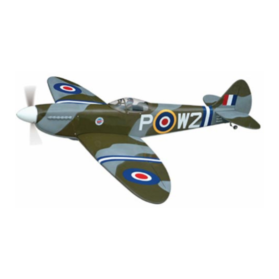
SPITFIRE 60
0.60 0.75 cubic inch displacement 2-stroke (glow)
0.70
0.81
cubic inch displacement 4 stroke (glow)
Requires:6-channel radio w/ 6 standard servos
and 1 low profile retract servo
Wing Span
Wing Area
Flying Weight
Fuselage Length
Warning! This model is not a toy.
It is designed for maximum performance. Please seek advice if one is not familiar with this kind
of engine powered precision model. Operating this model without prior preparation may cause
injuries. Remember,safety is the most important thing. Always keep this instruction manual
at hand for quick reference.
The World Models
Manufacturing Co., LTD.
www .thew orldm odels .com
Specifications
Specifications are subject to change without notice.
INSTRUCTION MANUAL
-
63.0 in / 1600 mm
704 sq in / 45.5 sq dm
7.5 lb / 3300 g
53.5 in /1350 mm
FACTORY PRE-FABRICATED
ALMOST-READY-TO-FLY (ARF) SERIES
MADE IN CHINA
Advertisement

Related Manuals for The World Models Manufacturing SPITFIRE - 60


Summary of Contents for The World Models Manufacturing SPITFIRE - 60
- Page 1 INSTRUCTION MANUAL SPITFIRE 60 0.60 0.75 cubic inch displacement 2-stroke (glow) 0.70 0.81 cubic inch displacement 4 stroke (glow) Requires:6-channel radio w/ 6 standard servos and 1 low profile retract servo Specifications Wing Span 63.0 in / 1600 mm Wing Area 704 sq in / 45.5 sq dm Flying Weight 7.5 lb / 3300 g...
-
Page 2: Before You Begin
SPITFIRE 60 I N D E X BEFORE YOU BEGIN P. 1 PARTS LIST P. 2 ASSEMBLY P. 3 -P.12 SAFETY PRECAUTIONS P. 12 BEFORE YOU BEGIN Read through the manual before you begin, so you will have an overall idea of what to do. Check all parts. -
Page 3: Parts List
Parts List 1. MAIN WING -- 1 pair 9. FUEL TANK 380cc -- 1 set PLYWOOD 2.7x37x99mm (For Fuel Tank Position Fixing ) -- 1 pc. 2. PLYWOOD 2x58x84mm (For Aileron Servo) -- 1 pair BALSA 8x18x21mm (For Aileron Servo Stand) -- 4 pcs 10. - Page 4 pre-glued Screw PWA2 x 8mm Screw PB2 x 20mm Balsa 8 x 18 x 21mm Plywood 2 x 58 x 84 mm Bottom View Lead to Aileron Servo Pushrod 1.8 x 85mm PWA 2 x 8mm Straper TWM Pl8210010 CLEVIS WRENCH PB 2 x 20mm Fuel Tube Ø6x5mm...
- Page 5 Please apply glue to all surfaces of wing joiner Flap and Retract Servos Wing Tube 16 x 404mm Please refer to attched sheet for linkage connector installation R-side L-side Wheels down Position Wheels up Position Lead to retract servo Select the servo horn that will give 26mm travel when rotates through 180 . Lead to Flap Servo Flaps up Flaps Down...
- Page 6 Retractable Landing Gear Cover RETRACTABLE Screw PWA 2.3 x 8mm LANDING GEAR COVER Screw PM 2 x 6mm PM 2 x 6mm M2 Nut Washer d2xD5mm d2 x 5mm Washer PWA 2.3 x 8mm PM 2 x 6mm Stabilizer / Elevator (Stabilizer) (Main Wing) B=B'...
-
Page 7: Elevator Pushrod
Vertical Fin / Rudder preglued C=C' Completed 1mm pilot holes for World Models control horn are pre-drilled. Elevator Pushrod Please look for pin-hole marks at under side of control surfaces. Screw PB2 x 16mm PB2 x 16mm 26mm Pushrod 1.8 x 645mm Clevis Fuel Tube 6 x 5mm... - Page 8 Fuel Tank 380cc Plywood 2.7 x 37 x 99mm Install Plywood 2.7 x 37 x 99mm (For fuel tank position fixing) Fuel Tank 380cc Bottom View Bottom View Engine Mount Inverted Mount M4x25mm Socket Head Screw Washer d4xD12mm M4 x 25mm d4 x D12mm Washer Engine Mount...
- Page 9 Engine Socket Head Screw M 3.5 x 30mm Washer d3.5xD8mm M3.5 M3.5 Nut d3.5xD8mm Washer M 3.5 x 30mm Plastic Tube d2xD3x120mm Throttle Pushwire 1.2 x 290mm Installed Engine position M3.5 Nut 138mm 5.43 in d3.5xD8mm Washer M3.5 x 30mm IIIustration is for inverted mounting.
- Page 10 Servo Set Set Screw M3 x 3mm Set Screw M3 x 3mm Linkage Connector Washer Retract Servo, Throttle Servo. Please refer to attached sheet for linkage connector installation. Install and arrange the servo as shown in the diagram. Servos Balsa 5 x 5 x 37mm Front Plywood 2.7 x 37 x 99mm...
- Page 11 Main Wing Washer d4 x D15mm Socket Head Screw M4X40mm M4x40mm d4 x D15mm Washer Balsa 16.2 80 x 103 mm Pilot Canopy Screw PWA 2.3 x 8mm Silicon Grommet d1.5xD6.5mm Place canopy on fuselage and drill pilot holes. PWA 2.3 x 8mm Apply double-sided tape Silicon Grommet d1.5xD6.5mm...
- Page 12 Wing Setting Adjust the wing and fuselage configuration as shown in the diagrams. P.11...
- Page 13 Control Throws Adjust the control throws as shown in the diagram. These throws are good for general Elevator flying. You can adjust according to your 20mm personal preference. 20mm Rudder 40mm 40mm Flaps (near fuselage) 24mm Ailerons (away from fuselage) 15mm 15mm The ideal C.G.
- Page 14 LINKAGE CONNECTOR HW7111050 & HW7111060 Drill 2mm hole at servo horn. Insert linkage connector into servo horn. Make sure shoulder of screw is cleared from servo horn. Add washer to reduce play if necessary. Shoulder Tighten up the round nut against the shoulder.
- Page 15 Product Registration Form (US Customers) We would like to share with you any relevant information regarding your model, including product news and free upgrade parts when applicable. Please fill in the following and send to Air orne Models, 2403 Research Drive, Livermore, CA 94550 USA 1.Name: 2.Address: 3.Phone #:...
-
Page 17: Optional Parts
Optional Parts ACCESSORIES) Fuel Filler 180mm Extension For Park Flyer Code No. Size Package Code No. Size Package PL8110030 15 x 22 x 49mm 1 x 1 pc KW0011800 180mm 1 set 180mm Y-Cord For Park Flyer Code No. Size Package KW0021800 180mm 1 pc... - Page 18 A127PO21370906...
Need help?
Do you have a question about the SPITFIRE - 60 and is the answer not in the manual?
Questions and answers