Table of Contents
Advertisement
Quick Links
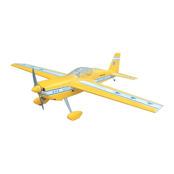
Extra Sports 30S
0 48 0 56 cubic inch displace ment 4 stroke
Radio Requires: 4 channel radiol w 4
Wing Span
Wing Area
Flying Weight
Fuselage Length
Wa r n i n g ! T h i s m o d e l i s n o t a t o y.
It is designed for maximum performance. Please seek advice if one is not familiar with this kind
of engine powered precision model. Operating this model without prior preparation may cause
injuries. Remember, safety is the most important thing. Always keep this instruction manual
at hand for quick reference.
Specifications
* Specifications are subject to change without notice.*
INSTRUCTION MANUAL
standard
52.0 in / 1320 mm
419 sq in / 27.0 sq dm
4.5 lbs / 2040 g
44.0 in / 1120 mm
FACTORY PRE-FABRICATED
ALMOST-READY-TO-FLY (ARF) SERIES
servos
MADE IN CHINA
Advertisement
Table of Contents

Related Manuals for The World Models Manufacturing Extra Sports 30S


Summary of Contents for The World Models Manufacturing Extra Sports 30S
- Page 1 Extra Sports 30S INSTRUCTION MANUAL 0 48 0 56 cubic inch displace ment 4 stroke Radio Requires: 4 channel radiol w 4 standard servos Specifications Wing Span 52.0 in / 1320 mm Wing Area 419 sq in / 27.0 sq dm Flying Weight 4.5 lbs / 2040 g...
-
Page 2: Before You Begin
Ext r a Spor t s - 3 0S I N D E X BEFORE YOU BEGIN P. 1 PARTS LIST P. 2 ASSEMBLY P. 3 - 11 SAFETY PRECAUTIONS P. 11 BEFORE YOU BEGIN Read through the manual before you begin, so you will have an overall idea of what to do. Check all parts. -
Page 3: Parts List
Parts List 1. MAIN WING -- 1 pair. 14.COWLING -- 1set TRANSPARENT DUMMY COWLING -- 1pc 2.RING Ø2.3mm -- 2 pcs. SCREW PWA2.6x12mm -- 4pcs WING TUBE Ø9.5x184mm -- 1 pc. SILICON GROMMET d1.5xD6.5mm -- 4pcs SPINNER Ø52mm -- 1 pc. 3.PLYWOOD 3x30x94mm (Wing Protection) -- 1 pc. - Page 4 Main Wing Securely glue together. If coming off during flights, you lose control of your airplane which leads to Cut out to fit in the aileron servo. accidents! Wing Tube 9.5 x 184mm Cut out to fit in the aileron servo. Main Wing Peel off shaded portion covering film.
-
Page 5: Main Landing Gear
Ailero Servo Straper Fuel Tube O6 x5mm Clevis Ring PM 3 x10mm Main Landing Gear PM 3 x10mm Screw Peel off shaded portion covering film. Main Landing Gear PM3.5x35mm PM 3.5 x35mm Screw 3.5mm Nut PA 3 x 6mm Screw PA 3 x6mm 3.5mm Washer 3.5mm Washer... -
Page 6: Vertical Fin
Securely glue together. If coming Stabilizer off during flights, you lose control of your airplane which leads to accidents! (Stabilizer) Temporary install the main wing, adjust leveling of the stabilizer to make it as (Main Wing) parallel to the main wing as possible. B=B' Elevator PM 2 x 12mm Screw... -
Page 7: Engine Mount
Ø1mm pilot holes for World Models tri-horn are pre-drilled. Please look Rudder for pin-hole marks at side of control surfaces. Screw P M 2 x 1 2 m m Screw PA 3 x 12mm Set Screw 3 m m Collar 2 . - Page 8 Engine Lead the 1.2mm throttle rod through the plastic tube and attach the throttle rod to the Screw throttle lever on the engine. P M 3 x 2 5 m m Washer 3 m m 3 m m 3 m m 3.5mm P M 3 x 2 5 m m Fire...
-
Page 9: Radio Equipment
Install and arrange the servo Radio Equipment as shown in the diagram. P l y w o o d 3 x 8 x 1 0 9 . 1 m m B a l s a 6 x 8 x 5 8 m m Throttle B a l s a 6 x 7 x 5 8 m m Servo... - Page 10 Cockpit PWA2.3 x 8mm S c r e w P W A 2 . 3 x 8 m m PWA2.3 x 8mm Canopy PWA2.3 x 8mm S c r e w P WA 2 . 3 x 8 m m 3.5mm d1.5xD6.5mm Silicon Grommet Wing Setting...
-
Page 11: Control Throws
Control Throws Adjust the control throws as shown in the diagram.These throws are good for general flying. You can adjust according to your personal preference. C . G . The ideal C.G. position is 80mm(3.15 in) behind the leading edge measured at where the wing meets the fuselage. - Page 12 LINKAGE CONNECTOR HW7111030 & HW7111060 Drill 2mm hole at servo horn. Insert linkage connector into servo horn. Make sure shoulder of screw is cleared from servo horn. Add washer to reduce play if necessary. Shoulder Tighten up the round nut against the shoulder.
Need help?
Do you have a question about the Extra Sports 30S and is the answer not in the manual?
Questions and answers