Icom iC-A14 Instruction Manual
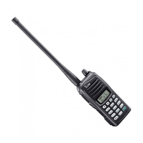
Vhf air band transceiver
Hide thumbs
Also See for iC-A14:
- Instruction manual (48 pages) ,
- Service manual (28 pages) ,
- Information (6 pages)

Related Manuals for Icom iC-A14


Summary of Contents for Icom iC-A14
- Page 1 INSTRUCTION MANUAL VHF AIR BAND TRANSCEIVER iA14 iA14S This device complies with Part 15 of the FCC Rules. Operation is subject to the condition that this device does not cause harmful inter- ference. YIC-A14 YIC-A14S...
-
Page 2: Safety Training Information
This radio has been evaluated for compliance at the distance of 2.5 cm with posure compliance requirements to be exceeded. The radio is transmit- the FCC RF exposure limits for “Occupational Use Only”. In addition, your Icom ting when “... -
Page 3: Foreword
FOREWORD SUPPLIED ACCESSORIES Thank you for purchasing this Icom product. The IC-A14/S The following accessories are supplied with the transceiver. is designed and built with Icom’s Qty. VHF AIR BAND TRANSCEIVER q Flexible antenna .............. 1 state of the art technology and craftsmanship. With proper w Battery pack* .............. -
Page 4: Precaution
Icom, Icom Inc. and the Icom logo are registered trademarks of Icom Incor- age the transceiver’s surfaces. porated (Japan) in Japan, the United States, the United Kingdom, Germany,... -
Page 5: Table Of Contents
…12 OPTIONS …………………………………………………………38 ■ Programming a memory channel ……………………………13 OPTIONAL HEADSET CONNECTION …………………………39 ■ Memory names …………………………………………………15 FOR CLASS B UNINTENTIONAL RADIATORS ……………40 ■ Copying memory contents ……………………………………16 ■ Clearing the memory contents (Available with the IC-A14 only) …………………………………………………………………… 17... -
Page 6: Panel Description
PANEL DESCRIPTION ■ Panel description q ANTENNA CONNECTOR [ANT] (p. 6) Connects to the supplied antenna. w KEY LOCK SWITCH [ ] (p. 9) ➥ Push to turn ON the key lock function. ➥ Hold down for 2 seconds to turn OFF the key lock func- tion. - Page 7 PANEL DESCRIPTION u KEYPAD (Available with only the IC-A14; pp. 3, 4) !0 EXTERNAL SPEAKER AND MICROPHONE JACKS [MIC/SP] (p. 39) i MEMORY MODE/MEMORY WRITE KEY [MR]/[MW] If desired, connects the optional speaker microphone or a Push to select the memory mode. (p. 12)
- Page 8 PANEL DESCRIPTION D KEYPAD (Available with IC-A14 only) ➥ Inputs digit “1” for frequency input or memory chan- ➥ Inputs digit “5” for frequency input or memory chan- nel selection. (pp. 8, 12) nel selection. (pp. 8, 12) ➥ Inputs “1,” “Q,” or “Z” when programming memory ➥...
- Page 9 PANEL DESCRIPTION ➥ Inputs digit “9” for frequency input or memory chan- nel selection. (pp. 8, 12) ➥ Inputs “9,” “W,” “X,” or “Y” when programming memory names. (p. 15) ➥ After pushing [FUNC], toggles scan tag setting ON or OFF. (p. 20) ➥...
-
Page 10: Function Display
ANL ICON (p. 22) Appears when the ANL (Automatic Noise Limiter) func- tion is in use. i WEATHER ALERT ICON (IC-A14 only) (p. 23) Appears when the weather alert function is in use. o LOCK ICON (p. 9) q FUNCTION ICON Appears when the lock function is in use. -
Page 11: Accessory Attachment
ACCESSORY ATTACHMENT D Antenna D Belt clip Insert the supplied antenna into the Conveniently attaches to your belt. antenna connector and screw down - To attach the belt clip q Remove the battery pack if it is attached. the antenna as shown at right. w Slide the belt clip in the direction of the arrow until the belt CAUTION! clip is locked and makes a ‘click’... - Page 12 ACCESSORY ATTACHMENT D Battery pack attachment Turn OFF the transceiver power by rotating [VOL] before at- taching or detaching the battery pack. To attach the battery pack: Slide the battery pack in the direction of the arrow (q), then lock it with the battery release button. •...
-
Page 13: Basic Operation
Push [Y]/[Z] to set the desired frequency. - For the IC-A14 only - • 1 MHz tuning step is selectable. Push [FUNC] , then push [Y]/[Z]. Push [FUNC] again to return to normal tuning. -
Page 14: Setting A Squelch Level
BASIC OPERATION ■ ■ Setting a squelch level Lock function The lock function prevents accidental frequency changes or The transceiver has a noise squelch circuit to mute undesired accidental function activation. noise while no signal is received. q Push [ q Push [SQLY] or [SQLZ] to select the squelch level. -
Page 15: Receiving
NOTE: About Time-Out-Timer function Appears when a signal is received. To prevent prolonged transmission, according to regula- tory requirements, the IC-A14/S has a Time-Out Timer function. This timer cuts OFF transmission after the set time period of continuous transmission. The Time-Out Timer is set in the Set mode. See page 26 When the squelch setting is too “tight”... -
Page 16: Side Tone Function
BASIC OPERATION ■ ■ Side tone function LCD backlight The IC-A14/S has an LCD backlight for convenience during When using a headset , the trans- (other manufacture’s products) night time operation. ceiver outputs your transmitted voice to the headset for mon- itoring. -
Page 17: Memory Operation
(Available with the IC-A14 only) and the IC-A14S has 100 memory chan- banks; default setting) A total of 200 memory channels in the IC-A14, are divided nels for storing often-used frequencies. into bank (up to 10 banks are selectable, depending on the q Push [MR] to select the memory mode. -
Page 18: Programming A Memory Channel
Program often-used frequencies using the following instruc- • EXAMPLE: Programming WX-05 into memory channel 9 tions. in memory BANK 3. D For the IC-A14 Push q Push [CLR] to select the frequency mode, if necessary. w Set the desired frequency. (p. 8) •... - Page 19 MEMORY OPERATION D For the IC-A14S q Push [CLR] to select the frequency mode, if necessary. • EXAMPLE: Programming 123.450 MHz into memory w Set the desired frequency. (p. 8) channel 51. e Hold down [MR] for 1 second to enter the select memory Push write mode.
-
Page 20: Memory Names
Select the desired memory channel to be programmed by same time. pushing [Y]/[Z] (or on only the IC-A14, push the keys on the • Return to the frequency display. keypad then [ENT]) • If no name is programmed, the programmed frequency is dis- r Push [MR] momentarily to enter the memory name pro- played. -
Page 21: Copying Memory Contents
Select the desired memory channel to be copied using For the IC-A14 [Y]/[Z] (or keypad and [ENT]; For the IC-A14 only) w Push [FUNC] then push [MW](MR). • Select the desired bank if desired. • The selected memory contents copied into frequency mode and frequency mode is selected automatically. -
Page 22: Clearing The Memory Contents (Available With The Ic-A14 Only)
MEMORY OPERATION ■ Clearing the memory contents (Available with the IC-A14 only) Unwanted memory channels can be cleared. q Select the desired memory channel to be cleared. (p. 12) • Select the desired bank if desired. (p. 12) w Push [FUNC] then hold down [CLR] for 1 second. -
Page 23: Scan Operation
Scan types COM band scan q Push [CLR] to select the frequency mode. The IC-A14 has 3 scan types to suit your needs. IC-A14S w Push [SQLY]/[SQLZ] to set the squelch level to the point has 2 scan types. where noise is just muted. -
Page 24: Memory Scan
Push [MR] to select the memory mode. channel mode. w Set squelch to the point where noise is just muted with • For the IC-A14, select the desired BANK if desired. (p. 12) w Push [SQLY]/[SQLZ] to set the squelch level to the point [SQLY]/[SQLZ]. -
Page 25: Tag" Channel Setting
The “TAG” channel function is only selectable in the nel. scan mode. *For the IC-A14 only e Hold down [LIGHT] for 2 seconds to set a “TAG.” r To cancel the “TAG” setting, repeat the above steps. The “... -
Page 26: Other Functions
The following transceiver’s settings will return to the default (Selectable on only the IC-A14) value; The IC-A14 can quickly be set to the 121.5 MHz emergency • Operating mode (Frequency, memory or weather* channel mode frequency. This function can be activated even when the key with frequency or channel number, including bank*) lock function is in use. -
Page 27: Key Touch Beep Tone
The beep tone, which sounds at the push of a switch can be The ANL (Automatic Noise Limiter) function reduces noise set, if desired. components such as that caused by engine ignition systems while receiving. For the IC-A14 ➥ Push [FUNC] then push [BEEP](8) to turn the key touch For the IC-A14 ➥... -
Page 28: Weather Channel Operation (Available With The Ic-A14 Only)
Weather channel operation (Selectable on only the IC-A14) D Setting weather alert function The IC-A14 has VHF marine WX (weather) channel receiving capability for fl ight planning. An NOAA broadcast station transmits a weather alert tone D Weather channel selection before any important weather announcements. -
Page 29: Duplex Operation (Available With The Ic-A14 Only)
OTHER FUNCTIONS ■ Duplex operation (Selectable on only the IC-A14) The duplex function allows you to call a fl ight service station while receiving a VOR station. The duplex function requires frequency programming for the fl ight service station in ad- vance. -
Page 30: Set Mode Setting
Push [CLR] to return to fre- quency mode. For the IC-A14 only Push [FUNC] then holding down [SET](ENT) for 1 second to • MIC— Microphone gain also enters into the Set mode. The internal microphone gain can be set to suit your needs. - Page 31 OTHER FUNCTIONS • I.MIC— Using the internal microphone The internal microphone can be turned OFF to use a head- set. This setting prevents unwanted audio or noise entering the internal microphone if the [PTT] is pushed. • TOT— Time-out timer Sets the time-out timer period to prevent prolonged transmis- sions, according to regulatory requirements.
-
Page 32: Battery Packs And Case
Icom radios or Icom charger. Only Icom battery packs are tested and approved for use and charge with Icom RDANGER! NEVER solder the battery terminals or NEVER radios or Icom charger. Using third-party or counterfeit bat- modify the battery pack. -
Page 33: Charging Caution
BC-179 (0°C to +40°C; +32°F to as below: +104°F). Icom recommends charging the battery at +20°C –20°C to +50°C; –4°F to +122°F (up to a month) (+68°F). The battery may heat up or rupture if charged out of –20°C to +35°C;... -
Page 34: Charging The Battery
BATTERY PACKS AND CASE ■ Charging the battery D Regular charging with the BC-179+BC-174 CAUTION! The BC-179 provides regular charging of battery packs. The • DO NOT modify the CP-22. A modifi cation could cause a fi re or following accessories are additionally required. electric shock. - Page 35 BATTERY PACKS AND CASE D AD-106 installation D Rapid charging with the BC-119N+AD-106 ➥ Connect the AD-106 charger adapter and the BC-119N or The optional BC-119N provides rapid charging of battery packs. The following accessories are additionally required. BC-121N as below (q), then install the AD-106 into the •...
-
Page 36: Battery Case (Optional For Some Versions)
BATTERY PACKS AND CASE ■ D Rapid charging with the BC-121N+AD-106 Battery case The optional BC-121N allows up to 6 battery packs to be (optional for some versions) charged simultaneously. The following are additionally re- D Precaution quired. • Six AD-106 charger adapters. NEVER incinerate used battery cells since internal battery •... - Page 37 BATTERY PACKS AND CASE D Alkaline cells installation w Install 6 AA (LR6) size alkaline cells. Install 6 AA (LR6) size alkaline cells as described below. q Release the latch, and open the cover. • Install the conventional alkaline cells only. •...
-
Page 38: Battery Packs And Case
BATTERY PACKS AND CASE D Battery case attachment Slide the battery case in the direction of the arrow. To release the battery case: • Slide the battery case until the transceiver’s battery release button Slide out the battery case’s battery release button in the di- makes a ‘click’... -
Page 39: Cloning
When cloning is fi nished, turn power OFF, then ON again to exit cloning mode. NOTE: Transceiver to transceiver cloning between IC-A14 OPC-474 and IC-A14S cannot be performed. w While pushing and holding [MR], rotate [VOL] to enter... -
Page 40: Cloning
CLONING D Cloning using PC Data can be cloned to and from a PC ® ® (Microsoft Windows using the optional CS-A14 2000/XP and Windows Vista™) CLON- and the optional OPC-478 ING SOFTWARE (RS-232C type) OPC-478UC . Consult the CS-A14 (USB type) CLONING CABLE HELP fi... -
Page 41: Troubleshooting
No beep sounds. • Beep tones turned OFF. • Turn the beep tone ON; IC-A14: Push [FUNC], then push [BEEP](8). p. 22 IC-A14S: Turn the beep tone ON in set mode. pp. 22, 25 D CP-22 fuse replacement If the fuse blows or the receiver stops functioning while oper- ating with the optional CP-22 , fi... -
Page 42: Specifications
IC-A14 • Intermediate frequencies : 1st 46.35 MHz, 2nd 450 kHz IC-A14S • Sensitivity • Power supply requirement : Specifi ed Icom’s battery packs COM band –6 dBµ typical (6 dB S/N) 7.4 V DC standard NAVI band –3 dBµ typical... -
Page 43: Options
OPTIONS D BATTERY PACKS D BELT CLIPS • MB-94 BELT CLIP • BP-230N/BP-232N/BP-232H Li-Ion BATTERY PACKS Alligator type belt clip. BP-230N: 7.4 V/980 mAh (typical); 950 mAh (minimum) • MB-96F LEATHER BELT HANGER BP-232N: 7.4 V/2000 mAh (typical); 1900 mAh (minimum) Attaches with the supplied belt clip (Fixed type). -
Page 44: Optional Headset Connection
OPC-499 HEADSET (Must be purchased separately) NOTICE! Some headsets do not work properly when used with the IC-A14/S. Therefore, ask your dealer for details about headsets com- Transceiver patible for operation with the IC-A14/S with the headset. -
Page 45: For Class B Unintentional Radiators
FOR CLASS B UNINTENTIONAL RADIATORS This equipment has been tested and found to comply with the limits for a Class B digital device, pursuant to part 15 of the FCC Rules. These limits are designed to provide reasonable protection against harmful interference in a residential instal- lation. - Page 46 MEMO...
- Page 47 MEMO...
- Page 48 A-6631H-1EX-w Printed in Japan © 2007–2013 Icom Inc. 1-1-32 Kamiminami, Hirano-ku, Osaka 547-0003, Japan Printed on recycled paper with soy ink.
Need help?
Do you have a question about the iC-A14 and is the answer not in the manual?
Questions and answers