Icom IC-A14 Service Manual
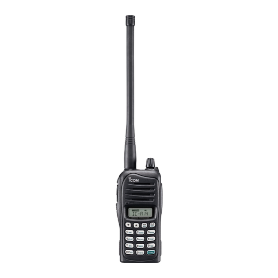
Vhf air band transceiver
Hide thumbs
Also See for IC-A14:
- Instruction manual (48 pages) ,
- Service manual (28 pages) ,
- Information (6 pages)
Advertisement
Table of Contents
Advertisement
Table of Contents

Subscribe to Our Youtube Channel
Related Manuals for Icom IC-A14


Summary of Contents for Icom IC-A14
- Page 1 VHF AIR BAND TRANSCEIVER S-14417XZ-C1 Jan. 2008...
-
Page 2: Ordering Parts
INTRODUCTION This service manual describes the latest service information for the IC-A14 and IC-A14S VHF AIR BAND TRANSCEIVER at the time of publication. MODEL VERSION KEY TYPE [USA] [USA-01] IC-A14 Full key [EXP] [EXP-01] [USA] [USA-01] IC-A14S Simple key [EXP]... - Page 3 CONTENTS SECTION SPECIFICATIONS SECTION INSIDE VIEWS SECTION DISASSEMBLY INSTRUCTION SECTION CIRCUIT DESCRIPITON RECEIVER CIRCUITS............4-1 TRANSMITTER CIRCUITS .
-
Page 4: Specifications
200 (20 CH × 10 BANKS) IC-A14 IC-A14S • Power supply requirement : Specifi ed Icom’s battery packs 7.4 V DC standard • Usable temperature range : –10˚C to +60˚C (+14°F to +140°F) • Current drain (at 7.4 V DC) : 1.5 A... -
Page 5: Disassembly Instruction
SECTION 3 DISASSEMBLY INSTRUCTION w Unsolder total of 8 points from the shield cover then 1. Removing the front panel q Remove the VR knob and antenna nut. remove it. e Unscrew 2 screws from the side plate then remove it. w Unscrew 2 screws from the bottom. - Page 6 S-14417XZ-C1 1-1-32, Kamiminami, Hirano-ku, Osaka 547-0003, Japan © 2008 Icom Inc.
- Page 7 Icom IC-A14 Service Manual Icom IC-A14 Service Manual Icom IC-A14 Service Manual Icom IC-A14 Service Manual Icom IC-A14 Service Manual Icom IC-A14 Service Manual Icom IC-A14 Service Manual Icom IC-A14 Service Manual Icom IC-A14 Service Manual...
Need help?
Do you have a question about the IC-A14 and is the answer not in the manual?
Questions and answers