Table of Contents
Advertisement
Advertisement
Table of Contents

Related Manuals for Icom IC-A15


Summary of Contents for Icom IC-A15
- Page 1 INSTRUCTION MANUAL VHF AIR BAND TRANSCEIVER iA15 iA15S YIC-A15 YIC-A15S...
-
Page 2: Important
Thank you for choosing this Icom product. The following accessories are supplied with the transceiver. This product is designed and built with Icom’ s state of the art technology and craftsmanship. With proper care, this prod- uct should provide you with years of trouble-free operation. -
Page 3: Country Code List
COUNTRY CODE LIST DISPOSAL • ISO 3166-1 The crossed-out wheeled-bin symbol on your product, literature, or packaging reminds you Country Codes Country Codes that in the European Union, all electrical and 1 Austria 18 Liechtenstein electronic products, batteries, and accumulators 2 Belgium 19 Lithuania 3 Bulgaria... -
Page 4: Precautions
CAUTION: DO NOT use harsh solvents such as Ben- Icom, Icom Inc. and the Icom logo are registered trademarks of Icom Incor- zine or alcohol to clean the transceiver, because they can porated (Japan) in Japan, the United States, the United Kingdom, Germany, damage the transceiver’s surfaces. -
Page 5: Table Of Contents
12. OPTIONAL HEADSET CONNECTION ����������36 4. MEMORY OPERATION ��������������� 12–17 ■ Memory channel selection ��������������12 ■ Memory bank selection (Selectable in only the IC-A15) ��12 ■ Entering a memory channel ��������������13 ■ Memory names �������������������15 ■ Copying memory contents ��������������16 ■... -
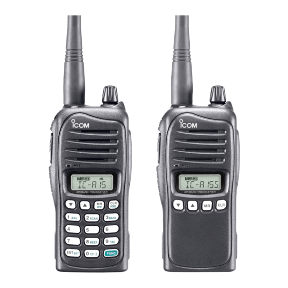
Page 6: Panel Description
PANEL DESCRIPTION ■ Panel description q ANTENNA CONNECTOR [ANT] (p. 6) Connects to the supplied antenna. w KEY LOCK SWITCH [ ] (p. 9) ➥ Push to turn ON the key lock function. ➥ Hold down for 2 seconds to turn OFF the key lock func- tion. - Page 7 PANEL DESCRIPTION !0 EXTERNAL SPEAKER AND MICROPHONE JACKS u KEYPAD (Available with only the IC-A15) (pp. 3, 4) [MIC/SP] (p. 36) i MEMORY MODE/MEMORY WRITE KEY [MR]/[MW] Connect the optional speaker microphone or a headset Push to select the memory mode. (p. 12)
- Page 8 PANEL DESCRIPTION D KEYPAD (Available with IC-A15 only) ➥ Inputs digit “1” for frequency entry or memory ➥ Inputs digit “5” for frequency entry or memory channel selection. (pp. 8, 12) channel selection. (pp. 8, 12) ➥ Inputs “1,” “Q,” or “Z” when entering memory ➥...
- Page 9 PANEL DESCRIPTION ➥ Inputs digit “9” for frequency entry or memory channel selection. (pp. 8, 12) ➥ Inputs “9,” “W,” “X,” or “Y” when entering memory names. (p. 15) ➥ After pushing [FUNC], toggles scan tag setting ON or OFF. (p. 19) ➥...
-
Page 10: Function Display
PANEL DESCRIPTION ■ Function display y ANL ICON (p. 21) Appears when the ANL (Automatic Noise Limiter) function is in use. u LOCK ICON (p. 9) Appears when the lock function is in use. i LOW BATTERY ICON (p. 11) ➥... -
Page 11: Accessory Attachment
ACCESSORY ATTACHMENT D Antenna D Belt clip Insert the antenna into the antenna Conveniently attaches to your belt. connector and screw down the an- - To attach the belt clip tenna, as shown to the right. q Remove the battery pack if it is attached. w Slide the belt clip in the direction of the arrow until the belt CAUTION! clip is locked and makes a ‘click’... -
Page 12: Accessory Attachment
ACCESSORY ATTACHMENT D Battery pack attachment Turn OFF the transceiver power by rotating [VOL] before attaching or detaching the battery pack. To attach the battery pack: Slide the battery pack in the direction of the arrow (q), then lock it with the battery release button. •... -
Page 13: Basic Operation
CH number appears on the function display. w Push [Y]/[Z] to set the frequency. - For the IC-A15 only - • The 1 MHz tuning step is selectable. Push [FUNC] , then push [Y]/[Z]. Push [FUNC] again to return to normal tuning. -
Page 14: Setting The Squelch Level
BASIC OPERATION ■ Setting the squelch level ■ Lock function The lock function prevents accidental frequency changes or The transceiver has a noise squelch circuit to mute the noise function activation. when no signal is received. q Push [ ] to turn ON the lock function. q Push [SQLY] or [SQLZ] to select the squelch level. -
Page 15: Receiving
NOTE: About Time-Out-Timer function To prevent prolonged transmission, according to regula- Appears when a signal is received. tory requirements, the IC-A15/S has a Time-Out Timer function. This timer cuts OFF transmission after the set time period. The Time-Out Timer is set in the Set mode. See page 23 for details. -
Page 16: Side Tone Function
BASIC OPERATION ■ Side tone function ■ LCD backlight The IC-A15/S has an LCD backlight for convenience during When using a headset , the transceiver outputs (user supplied) night time operation. your transmitted voice to the headset for monitoring. Connect... -
Page 17: Memory Operation
(Selectable in only the IC-A15) and the IC-A15S has 100 memory chan- banks, default setting) A total of 200 memory channels in the IC-A15, are divided nels for storing often-used frequencies. into bank (up to 10 banks are selectable, depending on the setting) for simple memory grouping. -
Page 18: Entering A Memory Channel
Enter often-used frequencies using the following instructions. • EXAMPLE: Entering 118.125 MHz into memory channel 9 in BANK 3. D For the IC-A15 Push q Push [CLR] to select the frequency mode, if necessary. w Set the frequency. (p. 8) e Push [FUNC], then push [MW](MR) to enter the select memory write mode. - Page 19 MEMORY OPERATION D For the IC-A15S q Push [CLR] to select the frequency mode, if necessary. • EXAMPLE: Entering 123.450 MHz into memory chan- w Set the frequency. (p. 8) nel 51. e Hold down [MR] for 1 second to enter the select memory Push write mode.
-
Page 20: Memory Names
Select the memory channel to be entered by pushing [Y]/ • If no name is entered, the entered frequency is displayed. (or on only the IC-A15, push the keys on the keypad then • To clear the entered memory names, push [CLR] before push- [ENT]) ing [ENT]. -
Page 21: Copying Memory Contents
Push [MR] to select memory mode. w Select the memory channel to be copied using [Y]/[Z] For the IC-A15 keypad and [ENT], For the IC-A15 only) w Push [FUNC], then push [MW](MR). • Select the bank. • The selected memory contents copied into frequency mode and frequency mode is selected automatically. -
Page 22: Clearing The Memory Contents (Selectable On Only The Ic-A15)
MEMORY OPERATION ■ Clearing the memory contents (Selectable on only the IC-A15) Unwanted memory channels can be cleared. q Select the memory channel to be cleared. (p. 12) • Select the bank. (p. 12) w Push [FUNC], then hold down [CLR] for 1 second. -
Page 23: Scan Operation
SCAN OPERATION ■ Scan types ■ Frequency scan The IC-A15/S has 2 scan types to suit your needs. q Push [CLR] to select the frequency mode. w Push [SQLY]/[SQLZ] to set the squelch level to the point FREQUENCY SCAN where noise is just disappears. -
Page 24: Memory Scan
The “TAG” channel function is only selectable in the scan mode. q Push [MR] to enter the memory mode. • For the IC-A15, select the BANK. (p. 12) For the IC-A15 w Push [SQLY]/[SQLZ] to set the squelch level to the point q Push [MR] to enter the memory mode. -
Page 25: Other Functions
(Selectable in only the IC-A15) The following transceiver’s settings will return to the default The IC-A15 can quickly be set to the 121.5 MHz emergency value. frequency. This function can be activated even when the key • Operating mode (Frequency or memory mode with frequency or lock function is in use. -
Page 26: Key Touch Beep Tone
The ANL (Automatic Noise Limiter) function reduces noise set. components on received signals, such as those caused by engine ignition systems. For the IC-A15 ➥ Push [FUNC], then push [BEEP](8) to turn the key touch For the IC-A15 beep tone ON or OFF. -
Page 27: Set Mode Setting
Push [CLR] to return to the frequency mode. • MIC— Microphone gain For the IC-A15 only The internal microphone gain can be set to suit your needs. Pushing [FUNC], then hold down [SET](ENT) for 1 second “H” , “M”... -
Page 28: Other Functions
OTHER FUNCTIONS • I.MIC— Using the internal microphone The internal microphone can be turned OFF to use a head- set. This setting prevents unwanted audio or noise from the inter- nal microphone when the [PTT] is pushed. • TOT— Time-out timer Sets the time-out timer period to prevent prolonged transmis- sions, according to regulatory requirements. -
Page 29: Battery Packs And Case
+60°C. High temperature buildup in an abnormal odor, heats up, or is discolored or deformed. If any of these conditions occur, contact your Icom dealer or the battery, such as could occur near fires or stoves, inside a sun heated vehicle, or in direct sunlight for long periods of distributor. -
Page 30: D Charging Caution
CAUTION: NEVER charge the battery outside of the spec- times you can charge the battery is between 300 and 500. ified temperature range: BC-179 (0°C to +40°C). Icom rec- Even when the battery appears to be fully charged, the oper- ommends charging the battery at +20°C. -
Page 31: Charging The Battery
BATTERY PACKS AND CASE ■ Charging the battery D Regular charging with the BC-179+BC-174 CAUTION! The BC-179 provides regular charging of battery packs. The • DO NOT modify the CP-22. A modification could cause a fire or following accessories are additionally required. electric shock. - Page 32 BATTERY PACKS AND CASE D Installing AD-106 D Rapid charging with the BC-119N+AD-106 ➥ Connect the AD-106 and the BC-119N The optional BC-119N rapidly charges the battery packs. The charger adapter following accessories are additionally required. or BC-121N as shown below (q). Then install the AD-106 •...
-
Page 33: Battery Case (Optional For Some Versions)
BATTERY PACKS AND CASE ■ Battery case D Rapid charging with the BC-121N+AD-106 The optional BC-121N allows up to 6 battery packs to be (optional for some versions) simultaneously charged. The following are additionally re- D Precaution quired. • Six AD-106 charger adapters. NEVER incinerate used batteries since internal battery gas •... - Page 34 BATTERY PACKS AND CASE D Alkaline batteries installation Install 6 AA (LR6) size alkaline batteries as described below. w Install 6 AA (LR6) size alkaline batteries. q Release the latch, and open the cover. • Install only conventional alkaline batteries. •...
-
Page 35: Battery Packs And Case
BATTERY PACKS AND CASE D Battery case attachment To attach the battery case: To detach the battery case: Slide the battery case in the direction of the arrow. Pull out the case’s battery release button in the direction of • Slide the case until the transceiver’s battery release button makes the arrow (q), and then push the release button in the direc- a ‘click’... -
Page 36: Cloning
ON again to exit the cloning mode. NOTE: Transceiver to transceiver cloning between the IC-A15 and the IC-A15S cannot be performed. OPC-474 e While holding down [MR], and rotate [VOL] to enter the cloning mode (for the master transceiver only). -
Page 37: Cloning
CLONING D Cloning using a PC Data can be cloned to and from a PC (Microsoft ® Windows ® using the optional CS-A14 2000/XP and Windows Vista™) CLON- and the optional OPC-478 ING SOFTWARE (RS-232C type) OPC-478UC . Consult the CS-A14 (USB type) CLONING CABLE HELP file for details. -
Page 38: Troubleshooting
13, 14 No beep sounds. • The beep tones are turned OFF. • Turn ON the beep tone, ➥ IC-A15: Push [FUNC], then push [BEEP](8). p. 21 ➥ IC-A15S: Turn ON the beep tone in the Set pp. 21, 22 mode. -
Page 39: Specifications
±5 ppm IC-A15S • Audio harmonic distortion: Less than 10% (at 85%+3 dB modula- • Power supply requirement: Specified Icom’s battery packs tion) 7.4 V DC standard • Harmonic spurious emissions: Less than –36 dBm (except operating • Usable temperature range: –20˚C to +55˚C... -
Page 40: Options
Available options may differ according to countries. Ask your autho- used with an Icom transceiver. Icom is not responsible for the destruction or damage to an Icom transceiver in the event it is used with equipment that is not rized dealer for details. -
Page 41: Optional Headset Connection
Use a PTT switch with a 3.5 mm ⁄ inch) diameter plug, required. OPC-499 HEADSET (Purchase separately) NOTICE! Some headsets do not work properly when used with the IC-A15/S. Transceiver Ask your dealer for details about headsets compatible with the IC-A15/IC-A15S. - Page 42 MEMO...
- Page 43 MEMO...
- Page 44 < Intended Country of Use > A-6632H-1EU-e Printed in Japan © 2008−2016 Icom Inc. 1-1-32 Kamiminami, Hirano-ku, Osaka 547-0003, Japan Printed on recycled paper with soy ink.
Need help?
Do you have a question about the IC-A15 and is the answer not in the manual?
Questions and answers