Sign In
Upload
Manuals
Brands
Inficon Manuals
Controller
IC6
Inficon IC6 Manuals
Manuals and User Guides for Inficon IC6. We have
1
Inficon IC6 manual available for free PDF download: Operating Manual
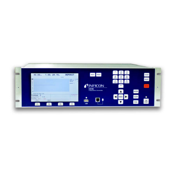
Inficon IC6 Operating Manual (342 pages)
Thin Film Deposition Controller
Brand:
Inficon
| Category:
Controller
| Size: 9.07 MB
Table of Contents
Table of Contents
9
Chapter 1 Introduction
21
Related Manuals
21
IC6 Safety
22
Definition of Notes, Cautions and Warnings
22
General Safety Information
23
Earth Ground
24
Main Power Connection
25
How to Contact INFICON
26
Returning Your IC6
26
IC6 Specifications
27
Measurement
27
Screens and Hierarchy
27
IC6 Features
28
Recipe Storage & Datalogging
28
Sensor Parameters
28
Source Parameters
28
Material Parameters
29
Introduction and Specifications
21
Process Layer Parameters/General Global Parameters
31
General Global Parameters
31
Display
33
DAC Outputs
34
Logic Processing
35
Relays / Inputs
35
Accessories
36
Operating Environment
36
Power
36
Remote Communications
36
Storage Temperature
36
Warm up Period
36
Installation Clearance Requirements
37
Size
37
Process Layer Parameters
31
Connector Clearances
37
Cooling Clearances
37
Cleaning
37
Weight
37
Base Configurations
38
Parts and Options Overview
38
Pre-Installed Options or Spares
38
Unpacking and Inspection
38
Optional Accessories
39
Oscillator Packages
39
Replacement Cables
39
Sensors
39
Initial Power-On Verification
40
Installation and Interfaces
43
Sensor Installation
43
Sensor Types
43
Avoiding Electrical Interference
46
IC6 Installation
46
Verifying/Establishing Earth Ground
46
Connections to Earth Ground
47
Minimizing Noise Pickup from External Cabling
48
Connecting the Controller
49
Interface Cable Fabrication and Pin-Out
49
Routing XIU Cables
49
Source Control Connection
49
Crucible Indexer Connections
50
DAC Option Kit 781-504-G1
50
I/O Expansion Options
51
RS-232C Communications
53
Isolated +24 V (DC) Supply
54
Operation
55
Sensor Information Rate/Xtal Display Description
63
Crystal Life and Starting Frequency
65
Percent Life Auto-Zero
65
Chapter 2 Location Guidelines
43
Function Key Selection Choices for the Sensor Information Rate/Xtal Display
66
Sensor Information Type/Freq Display Description
67
Test Xiu
68
Sensor Screen
68
Source
70
Material
71
Overview Page
71
Sensor Page
71
Source Page
71
Deposit Page
72
Pre/Post Page
72
Lib A-Hf, Lib Hf-Sc, Lib Sc-Z Sub-Displays
73
Overview Page
73
Process
73
Current Process
74
Etc. Screen
74
General
74
Process Page
74
Comm Page
76
Dacs Page
76
Date/Time Page
76
Lock Page
76
Message Page
76
Test Page
76
Audio/Visual Page
77
Digital I/O
77
Counter / Timer
78
Logic
78
Maintenance
78
USB Storage
78
Defining a Process
79
Process Description
79
Executing a Process
81
Co-Deposition
83
Pre-Conditioning a Layer
83
Automating a Process
84
Multiple Layer Starts
84
State Descriptions
86
Crystal Switching
88
Special Features
88
Xtaltwo (Crystaltwo)
89
Xtal12 (Crystal12)
90
Xtalsix (Crystalsix)
90
Generic Sensor Crystal Switching
91
Source/Crucible Selection
91
Example: Programming Turret Source Crucible Selection
92
Auto-Z
93
Auto Tune - Optimizing the Control Loop
94
Handheld Controller
94
Rate Watcher
94
Determining Soak Power with the Handheld Controller
95
Test Mode
95
Standard or Time Compressed
95
Advanced Test
96
USB Storage Device
96
Datalog
97
Lock and Access Codes
97
DAC Monitoring
100
Sensor & Source Set-Up
101
Recorder Function
114
Recorder Output
114
Recorder Range
114
Pre/Post Screen Deposit
120
Post Deposit Parameters
123
Deposit
124
Process Set-Up
129
Layer Parameters
131
Chapter 3
55
Front Panel Controls
55
Rear Panel Interfaces
57
Displays
59
Main Menu Display
59
Operate
60
Sensor Information
63
Chapter 4 Sensor Set-Up Introduction
101
Sensor Display Navigation
101
Sensor Parameters
102
Source Set-Up Introduction
104
Source Navigation
104
Source Parameters
105
DAC Output Selection Rules
107
Material Set-Up
109
Chapter 5 Introduction
109
Material Screen Overview Page
109
Material Definition
110
Material Screen Source
111
Material Screen Sensor Parameters Page
114
Layer Parameter Editing
131
Layer Parameters
132
Final Thick(Ness)
132
Material
132
Thick(Ness) Limit
132
Codep(Osition)
133
Cruc(Ible)
133
Ratio C(O)Ntr(O)L
133
Skip Deposit
133
Special Layer Parameter Features
133
Active Process
135
General Parameters
135
Chapter 6
129
Process Set-Up Introduction
129
Overview Page
129
Curr(Ent) Proc(Ess) Page
130
Process Layers 1 - 10 Etc
131
Chapter 7
135
General Screen Process Page
135
General Set-Up Overview
135
Auto Start Next (Layer)
136
Layer to Start
136
Layers Displayed
136
Active Layer Output
137
Dacs
137
Comm
138
Test
138
MESSAGE Page Set-Up
140
DATE / TIME Set up
141
Advanced Test
142
TEST Page Set up
142
Time Compressed
142
LOCK Page Code Set-Up
143
AUDIO / VISUAL Page Set up
144
Audio Feedback
144
Chapter 8
145
Max Concurrent Layer
136
All Input Page
145
Digital I/O Screen
145
All Output Page
146
I/O Board Page
147
Output Type
147
Logic Statement Set-Up
149
Logic Statement Groups
151
Logic Statement Editing
152
AND/OR and on Logic Connectors
154
Chapter 9
149
Logic Statement Overview
149
Editing the Logic Statements
150
ON Operator
154
IF Event Definitions
155
THEN Action Definitions
164
Logic Statement Example
168
Remote Communications
171
RS-232C Serial Port
171
TCP/IP Ethernet Port
172
Chapter 10
171
Physical Connections
171
Remote Communication Configuration Overview
171
How to Set up the Network Protocol on the PC
172
Message Format
175
Protocol
175
Network Connection
172
Command Packet (Host to IC6 Message)
175
Response Packet (IC6 to Host Message)
177
Timeouts
178
Data Type Codes
178
Encode
179
Integer
179
Lockcode
179
Communication Commands
180
Query and Update Commands
180
HELLO Command
181
Query Source Parameter
181
Status Commands
181
Update Source Parameter
182
Query General Parameter
183
Update General Parameter
183
Real_Xxx and Real_Xfx
179
Time
179
USB Datalog Format
184
DAC 1 to 12 Scale
185
Query Input Name
187
Query Process Name
187
Update Input Name
187
Update Process Name
187
Query Logic Statement
188
IC6 Event List
190
Update Logic Statement
190
IC6 Action List
194
Query Material Parameter
196
Update Material Parameter
196
Query Material Name
206
Query Output Name
206
Update Material Name
206
Update Output Name
206
Query Process Layer Parameter
207
Update Process Layer Parameter
207
Query Sensor Parameter
208
Update Sensor Parameter
208
Query Output Type
210
Query User Message
210
Update Output Type
210
Update User Message
210
Status General
211
Status Layer
214
Status Sensor
216
Remote General Action
219
Remote Layer Action
222
IC6 Communications Examples
224
General Command Packet Format
224
General Response Packet Format
224
HELLO Command, ASCII Name and Version
224
Query General Parameter
225
Update General Parameter
225
Query Material Parameter
225
Query Sensor Parameter
225
Update Material Parameter
225
Update Sensor Parameter
226
Query Process Layer Parameter
226
Query Source Parameter
226
Update Source Parameter
226
Update Process Layer Parameter
227
Query Input Name
228
Query Material Name
228
Query Process Name
228
Update Material Name
228
Update Process Name
228
Query Output Name
229
Query Output Type
229
Update Input Name
229
Update Output Name
229
Update Output Type
229
Query Logic Statement
230
Query User Message
230
Update User Message
230
Status General
231
Update Logic Statement
231
Remote General Action
232
Remote Layer Action
232
Status Layer
232
Status Sensor
232
Example for Interpreting Float Responses
233
Chapter 11 Multiple Sensor Deposition Control
235
IC6 Parameters and Corrections for Multiple Sensor Operation
237
Trend Analysis
239
IC6 Parameters Associated with the Trend Analysis Feature
239
IC6 Cygnus Emulation
240
IC6 Four & Six Layer (Cygnus Emulation) Configuration
241
Configure Sensors 1 to 6
242
Configure Six Materials
242
Configure Sources 1 to 6
242
Configure the Process
243
General Parameters
243
Logic Functions Table
243
Idle
244
Maintenance and Calibration Procedures
245
Chapter 12
245
Nondepcntl State
244
State Descriptions
244
Suspend
244
Determining Density
245
Importance of Density, Tooling and Z-Ratio
245
Determining Tooling
246
Laboratory Determination of Z-Ratio
247
Autotune Preparation Instructions
249
Autotuning
249
Autotune Parameters
252
Autotune Manual Display
253
Autotune Description
254
Determining Cross Talk Calibration
257
For Co-Deposition
257
Autotune Tuning Display
254
Cross Talk Calibration Procedural Notes
258
Procedure Set-Up
258
Cross Talk Calibrate Parameters
260
Cross Talk Calibration MANUAL Display
261
Function Key Selection Choices
261
Cross Talk Calibration CALIBRATE Display
262
Cross Talk Calibration SELECT Display
263
Function Key Selection Choices for Cross Talk Calibration Select
263
Source Maintenance
264
Source Maintenance Parameters
265
Crucible Rotation
265
Start/Stop Manual Power
265
System Status
266
Counters & Timers
267
Directory Structure
269
USB Storage Devices
269
Configuration Files
270
Data Logs
271
Screen Captures
272
Status Messages
273
Troubleshooting, Status and Error Messages
273
User Messages
277
Autotune and Calibration Messages
278
STOP Messages
279
Transient Messages
281
Input Error Messages
286
Troubleshooting Guide
288
Troubleshooting the IC6
289
Troubleshooting Transducers/Sensors
292
Troubleshooting Computer Communications
296
Front Load
299
Replacing the Crystal
299
Cool Drawer
300
Bakeable Sensor
302
Shuttered and Dual Sensors
302
Sputtering Sensor
303
Crystal Snatcher
304
Crystalsix (Xtalsix)
304
Crystal Sensor Emulator IPN 760-601-G1 or 760-601-G2
305
Diagnostic Procedures
306
Chapter 13 Introduction
267
Toggle Sensor and Source Shutter
265
Chapter 14 File Handling (USB)
269
USB Storage
269
Measurement System Diagnostic Procedure
306
Feedthrough or In-Vacuum Cable
307
Diagnostic Procedure
307
Sensor Head or Monitor Crystal Diagnostic Procedure
308
System Diagnostics Pass but Crystal Fail Message Remains
309
XTAL Life
309
Sensor Cover Connection
310
Compatible Sensor Heads
310
Incompatible Sensor Heads
310
Specifications
311
Measurement and Control Theory
313
Monitor Crystals
314
Period Measurement Technique
316
Z-Match Technique
317
Active Oscillator
318
Modelock Oscillator
319
Auto-Z Theory
321
Control Loop Theory
323
Material Table
329
Chapter 15
273
Chapter 16 Basics
313
Appendix A
329
Introduction
329
A.1 Introduction
329
Advertisement
Advertisement
Related Products
Inficon IF300P
Inficon IC1000
Inficon IRwin S
Inficon IRwin SX
Inficon IRwin SXT
Inficon IRwin SXG
Inficon IRwin SXGT
Inficon Sensistor ISH2000P
Inficon Sensistor ILS500 F
Inficon IMM-200
Inficon Categories
Security Sensors
Measuring Instruments
Controller
Test Equipment
Gas Detectors
More Inficon Manuals
Login
Sign In
OR
Sign in with Facebook
Sign in with Google
Upload manual
Upload from disk
Upload from URL