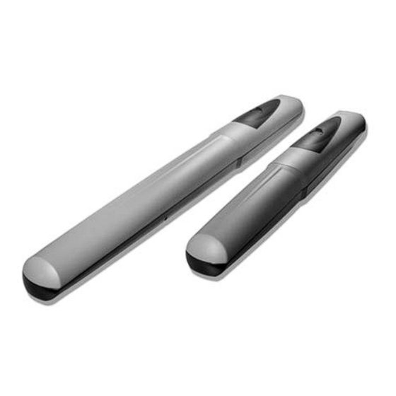
CAME AX5024 Installation Manual
Automation for swing gates
Hide thumbs
Also See for AX5024:
- Installation manual (22 pages) ,
- Installation manual (16 pages) ,
- Installation manual (65 pages)
Summary of Contents for CAME AX5024
- Page 1 AUTOMATION 11 9 D U86EN FOR SWING GATES INSTALLATION MANUAL AX3024 / AX5024 English...
-
Page 2: Read Carefully
• If repairs or modifi cations are required to the system, release other use is dangerous. CAME Cancelli Automatici S.p.A is not liable for any the operator and do not use it until safety conditions have been restored • Cut damage caused by improper, wrongful and unreasonable use •... -
Page 3: Legend Of Symbols
But whereas with reversible operators it is merely advisable, with irreversible ones, beyond 4 m, it is obligatory. 3 Reference Standards The company CAME cancelli automatici is ISO 9001 quality certified; it has also obtained the ISO 14001 environmental safeguarding certification. CAME engineers and manufactures all of its products in Italy. -
Page 4: Technical Features
4.2 Technical features GEARMOTOR AX3024 / AX5024 Control board power supply: 230V A.C. 50/60Hz Motor power supply: 24V D.C. Max draw.: 10A Power: 240W Adjustable thrust: 500÷4500N Opening time(90°): adjustable Duty cycle: intensive user Protection rating: IP44 4.3 Description of parts... -
Page 5: Installation
5 Installation Installation must be carried out by expert qualified personnel and in full compliance with current regulations. 5.1 Preliminary checks Before installing, do the following: • Make sure you have suitable tubing and conduits for the electrical cables to pass through and be protected against mechanical damage;... -
Page 6: Standard Installation
5.4 Standard installation 1) AXO operator 2) Control panel 3) Reception antenna 4) Flashing light 5) Selector switch 6) Photocells 7) Electric cable junction box 8) Mechanical gate stops 9) Photocell column 5.5 Installing the operator The following illustrations are only examples, given that the space available for anchoring the operator and accessories may vary from gate to gate. - Page 7 Note: by increasing measure B, the opening angle and gate speed are reduced, while the gearmotor thrust is increased. By increasing the measure A, the opening angle and gate speed are increases, while the gearmotor thrust is decreased. Pillar bracket Gate bracket AX3024 AX5024 Gate leaves of up to 3m Gate leaves of up to 5 m Opening C max...
- Page 8 Weld the gate bracket to the gate leaf making sure the quotas shown in the table are met. Note: for AX5024 gearmotors, require an additional 10 mm shim between the gate and the bracket. Note: on non-metal gate leaves assemble and weld the two parts of the bracket and secure them with proper screws.
- Page 9 Open the gate leaf and insert the pin into the gate bracket and secure it using a washer and nut. Gate bracket UNI6593 Ø8 washer Screw UNI5739 M8x10 Release the gearmotor (see paragraph on manual release), completely open the gate leaf, loosen the nuts of the opening mechanical stop and position it up against the attachment pin, then secure it.
- Page 10 5.6 Manual release of the gearmotor Slide open the small door that protects the release, insert the tri-lobed key and turn it. 5.7 Connecting to the control panel For the electrical connection procedures, use the junction box and branching boxes. Connecting the 24V d.c.
- Page 11 Pillar bracket Extra bracket For AX5024 gearmotors, directly secure the standard issue bracket to the pillar without using the supplementary bracket, while taking into account the measurements shown in table 2. Finally, secure the gearmotor to the brackets with the issued screws and washers.
- Page 12 Fully close the gate-leaf, place the mechanical stop against it with the pin attachment and fi x it in place. Attachment pin Opening mechanical stop Fully open the gate-leaf, place the mechanical stop against it with the pin attachment and fi x it in place. Attachment pin Closing mechanical stop Connect the gearmotors to the panel as shown in the diagram.
-
Page 13: Maintenance
7 Maintenance Extraordinary maintenance Before doing any maintenance, cut off the power supply, to prevent any hazardous situations caused by accidentally activating the operator. ☞ Periodic maintenance log kept by users (every six months) Date Notes Signature Extraordinary maintenance The following table is for logging any extraordinary maintenance jobs, repairs and improvements performed by specialized contractors. ... - Page 14 ☞ CAME CANCELLI AUTOMATICI S.p.A. employs a certified Environmental Management System at its premises, compliant with the UNI EN ISO 14001 standard to ensure the environment is safeguarded. Please continue safeguarding the environment. At CAME we consider it one of the fundamentals of our operating and market strategies. Simply follow these brief disposal guidelines:...
- Page 16 HR • Za sve dodatne informacije o poduzeću, proizvodima i tehničkoj podršci: UK • Для отримання будь-якої іншої інформації про компанію, продукцію та технічну підтримку: www. came.com www. came.com CAME Cancelli Automatici S.p.A. CAME Cancelli Automatici S.p.A. Via Martiri Della Libertà, 15 31030 Dosson Di Casier...


Need help?
Do you have a question about the AX5024 and is the answer not in the manual?
Questions and answers