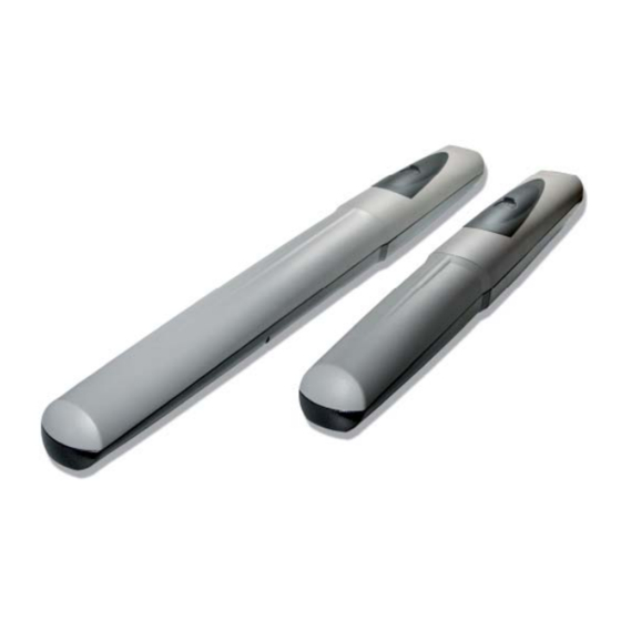
CAME AX3024 Installation Manual
Operator for swing gates
Hide thumbs
Also See for AX3024:
- Installation manual (22 pages) ,
- Installation manual (16 pages) ,
- Installation manual (65 pages)
Table of Contents
Advertisement
Quick Links
Advertisement
Table of Contents

Summary of Contents for CAME AX3024
- Page 1 Operator FA01165-EN for swing gates AX3024/AX5024 EN English INSTALLATION MANUAL...
- Page 2 USED PURPOSE OPERATION TO DO WITH THE POWER ON ONSTANTLY CLEAN THE PHOTOCELLS WHICH IT WAS EXPLICITLY DESIGNED NY OTHER USE IS DANGEROUS CAME S. GLASS COVERS USING A SLIGHTLY WATER MOISTENED CLOTH DO NOT USE SOLVENTS LIABLE DAMAGE CAUSED •...
- Page 3 ☞ This symbol shows which parts to tell users about. DESCRIPTION AX3024 Irreversible gearmotor for swing gates with leaves of up to 3 m long. AX5024 Irreversible gearmotor for swing gates with leaves of up to 5 m long. Intended use This gearmotor is designed to power and operate swing gates in private homes and apartment blocks.
- Page 4 Dimensions (mm) AX3024 AX5024 1100 1180 Description of parts Operator M6X20 UNI5739 screws for mechanical stop Pilaster bracket 10. Endless screw pin Gate bracket 11. Ø8x24 UNI6593 washer M8x35 UNI5737 screw for securing pillar bracket 12. Gate bracket screw for securing to M8x10 UNI5739 pin Bushing 13.
- Page 5 Standard installation AXO operator Control panel Reception antenna Flashing light Selector switch Photocells Electric cable junction box Mechanical gate stops Photocell column GENERAL INSTALLATION INDICATIONS Only skilled, qualified staff must install this product. Preliminary checks Before beginning, do the following: •...
-
Page 6: Installation
The number of tubes depends on the type of system and the accessories you are going to fit. Fastening the braces Establish the point the gate and post braces will be fitted, while respecting the quotas shown on the table. Post bracket Gate bracket AX3024 AX5024... - Page 7 Application dimension (mm) AX3024 Leaf opening arc (°) C MAX 90° 120° 120° AX5024 Leaf opening arc (°) C MAX 90° 1100 120° The greater the gate leaf's opening angle, the greater the opening speed and the slower is the gearmotor's thrust.
- Page 8 Insert the bushing (lubricated) into the pillar bracket’s hole. The bracket has holes that allow the opening angle to be changed. Secure the tail joint to the bracket. Screw M8 x 35 Bushing Tail joint Nut UNI 7474 M8 AX3024 Bushing Tail joint AX5024...
- Page 9 Open the gate leaf and insert the pin into the gate bracket and secure it using a washer and nut. Gate bracket UNI6593 Ø8 washer Screw UNI5739 M8x10 Release the gearmotor (see paragraph on manual release), completely open the gate leaf, loosen the nuts of the opening mechanical stop and position it up against the attachment pin, then secure it.
- Page 10 RELEASING THE GEARMOTOR This procedure must be done with the main power cut off . The gearmotor's manual release may cause unwanted movement of the gate, if the latter has any mechanical issues or if it is not balanced. Slide open the small door that protects the release, insert the tri-lobed key and turn it. Connecting to the control panel Warning! Before working on the control panel, cut off the main current supply and, if present, remove any batteries.
- Page 11 INWARD OPENING CONNECTIONS AND INSTALLING (non-issued) Supplementary bracket TABLE 1 TABLE 2 Opening Opening (mm) (mm) (mm) (mm) (mm) (mm) 90° 1100 90° Fastening the braces Weld pillar bracket to the non-issued supplementary bracket, while gate is open, then secure the brackets to the pillar, making sure the “A” and “B”...
-
Page 12: Troubleshooting
Fully close the gate-leaf, place the mechanical stop against it with the pin attachment and fi x it in place. Opening mechanical Attachment pin stop Fully open the gate-leaf, place the mechanical stop against it with the pin attachment and fi x it in place. Attachment pin Closing mechanical stop Connect the gearmotors to the panel as shown in the diagram. -
Page 13: Maintenance
MAINTENANCE Periodic maintenance ☞ Before doing any maintenance, cut off the power supply, to prevent any hazardous situations caused by accidentally activating the operator. Periodic maintenance log kept by users (every six months) Date Notes Signature... - Page 14 Extraordinary maintenance The following table is for logging any extraordinary maintenance jobs, repairs and improvements performed by specialized contractors. Any extraordinary maintenance jobs must be done only by specialized technicians. Extraordinary maintenance log Fitter's stamp Name of operator Job performed on (date) Technician's signature Requester's signature Job performed __________________________________________________________________________________________...
-
Page 15: Dismantling And Disposal
DISMANTLING AND DISPOSAL ☞ CAME S.p.A. applies a certified Environmental Management System at its premises, which is compliant with the UNI EN ISO 14001 standard to ensure the environment is safeguarded. Please continue safeguarding the environment. At CAME we consider it one of the fundamentals of our operating and market strategies. Simply... - Page 16 The contents of this manual may change, at any time, and without notice. CAME S.p.A. Via Martiri Della Libertà, 15 31030 Dosson di Casier - Treviso - Italy tel. (+39) 0422 4940 - fax. (+39) 0422 4941...


Need help?
Do you have a question about the AX3024 and is the answer not in the manual?
Questions and answers