Table of Contents
Advertisement
Quick Links
Advertisement
Table of Contents

Related Manuals for Heatrae Sadia Aquatap Boil and Chill


Summary of Contents for Heatrae Sadia Aquatap Boil and Chill
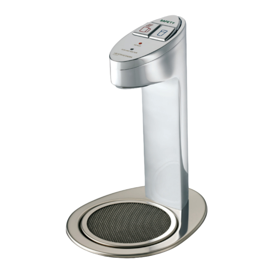
- Page 1 Aquatap (Boil and Chill / Boil and Ambient) Installation and user manual...
-
Page 2: Table Of Contents
CONTENTS SECTION PAGE 1.0 INTRODUCTION 2.0 TECHNICAL SPECIFICATION 3.0 INSTALLATION - IMPORTANT INSTALLATION POINTS 4.0 INSTALLATION - MOUNTING THE WATER HEATING UNIT 5.0 INSTALLATION - WATER SUPPLY 6.0 INSTALLATION - VENT PIPE 7.0 INSTALLATION - DISPENSING TAP MOUNTING 8.0 INSTALLATION - DISPENSING TAP CONNECTION 9.0 INSTALLATION - ELECTRICAL REQUIREMENTS 10.0 COMMISSIONING 11.0 USER INSTRUCTIONS... -
Page 3: Introduction
BOIL AND CHILL MODEL (INCLUDING BOIL AND AMBIENT) 1.0 INTRODUCTION Thank you for purchasing a Heatrae Sadia Aquatap unit. This unit is manufactured to the highest standards and has been designed to meet all the latest relevant constructional and safety specifications. -
Page 4: Technical Specification
2.0 TECHNICAL SPECIFICATION AQUATAP HEATER Model reference 95200262 Boil and Chill 95200263 Boil and Ambient Electrical rating 2.3kW @ 230 V ~ 2.5kW @ 240 V ~ Nominal capacity 5.0 litres Weight (full) 17.5kg Rated pressure 0 MPa ( 0 bar ) Minimum supply pressure 0.05 MPa ( 0.5 bar ) - Page 5 FIGURE 2: AQUATAP HEATER - IMPORTANT FEATURES STEAM CONDENSING TRAP THERMAL CUT-OUT AMBIENT / COLD MAIN PCB WATER SOLENOID INLET SOLENOID LEVEL SENSOR ASSEMBLY PUMP DRAIN AMBIENT / COLD WATER PCB TRANSFORMER HEATING ELEMENT...
- Page 6 FIGURE 3: AQUATAP WATER HEATER SCHEMATIC OVER STEAM CONDENSING TRAP TEMPERATURE SENSOR LEVEL HOT WATER STORE SENSOR SOLENOID VALVE HEATING ELEMENT LEVEL SENSOR PUMP SOLENOID VALVE...
-
Page 7: Installation - Important Installation Points
IMPORTANT INSTALLATION POINTS The Aquatap unit must be installed in accordance with the relevant requirements of: • The appropriate building regulations by application of either The Building Regulations (England and Wales), The Building Regulations (Scotland) or The Building Regulations (Northern Ireland). In territories other than those listed the local regulations in force must be complied with. -
Page 8: Installation - Mounting The Water Heating Unit
INSTALLATION – MOUNTING THE WATER HEATING UNIT The Aquatap water heating unit is free standing and must be positioned on a level surface. If being mounted in a cupboard, shelf unit or false base, ensure that the supporting surface can carry the full weight of the unit (see TECHNICAL SPECIFICATIONS section 2.0, page 4) Refer to fig. -
Page 9: Installation - Water Supply
5.0 INSTALLATION - WATER SUPPLY The INLET connection to the Aquatap water heating unit is located on the top rear of the unit (see fig. 1, page 4). It is threaded ½” BSP male parallel flat faced fitting. Any connection must use a suitable WRAS listed sealing washer. It is not possible to make a compression connection directly to the INLET connection. -
Page 10: Installation - Vent Pipe
INSTALLATION – VENT PIPE The VENT connection from the Aquatap water heating unit is located on the top rear of the unit (see fig. 1, page 4). It is a hose spigot to which the flexible VENT hose of the dispensing tap is attached. Refer to section 7.0 INSTALLATION – DISPENSING TAP MOUNTING below &... - Page 11 FIGURE 5 : TAP MOUNTING SEALING WASHER WORK TOP “C” CLAMP 35mm HOLE 35mm HOLE SECURING NUT HOT PIPE COLD/AMBIENT PIPE VENT PIPE FIGURE 6 : DISPENSER DIMENSIONS 60.0 61.0...
-
Page 12: Installation - Dispensing Tap Connection
INSTALLATION – DISPENSING TAP CONNECTION The hot supply hose should be connected to the OUTLET hose spigot of the Aquatap water heating unit. The hose should rise continuously from the heater to the tap without kinks or twists. If necessary it can be cut to a shorter length, but it should never be lengthened. - Page 13 Plug the dispensing tap cable connector into the Aquatap heater. Plug the Aquatap into a 13A socket. If a chiller unit is fitted to the dispenser, site the chiller near to the Aquatap heater, make sure that the chiller level tube is facing outwards to allow servicing. Connect the water supply to the chiller as per fig 8.
-
Page 14: Installation - Electrical Requirements
INSTALLATION – ELECTRICAL REQUIREMENTS WARNING: This appliance must be earthed. It is suitable for a 230 / 240 V ~ SUPPLY ONLY. Installation must be carried out by a competent electrician in accordance with the latest edition of BS 7671 (the IEE Wiring Regulations). The Aquatap heater is supplied with a 1.2 metre mains cable fitted with a 3-pin UK moulded mains plug. -
Page 15: Commissioning
10.0 COMMISSIONING 10.1 The Aquatap heater incorporates an electronic controls system which has a self- commissioning and calibration function. No installer or user adjustment is necessary before use. 10.2 Check that all electrical, water and vent pipe connections have been correctly made and are secure (ensure the pipes between the heater and the dispense tap rise continuously). - Page 16 FIGURE 10: WIRING DIAGRAM PCB PLUG FUNCTIONS P1 - TRANSFORMER 9v CONNECTION - POWER LED ORANGE P2 - PCB LINK CONNECTIONS (P2 - J4 ) - POWER LED BLACK P3 - LED WIRING CONNECTOR - READY LED BLACK J5 - TEMPERATURE & LEVEL CONTROL - READY LED BLUE CONNECTOR - BLACK...
- Page 17 TOP COVER FIGURE 11 : FRONT COVER REMOVAL SECURING SCREWS MAIN COVER HOOK TOP EDGE OF FASCIA INTO COVER APERTURE ORANGE LED (TOP) BLUE LED (BOTTOM) FASCIA SECURING SCREW COVER SECURING SCREWS 10.6 The “TEMPERATURE READY” indicator light on the Aquatap heater unit and the “READY”...
- Page 18 10.7 The “READY” indicators will continue to flash until the heater unit is full and has self - calibrated to the correct boiling temperature. At this point, the “READY” indicators will stop flashing and remain illuminated. If the calibration procedure is interrupted the light will continue to flash until the unit has calibrated.
-
Page 19: User Instructions
10.12 The commisioning record should be completed (see section 15.0, page 31). 10.13 These instructions should be left with the user for future reference. 11.0 USER INSTRUCTIONS 11.1 Once installed and commissioned, the filling and heating cycles of the Aquatap are completely automatic.The indicator lights on the dispensing tap will indicate the status of the system. -
Page 20: Maintenance
Normal Operation Indication Description Boiling water light (dispenser) Steady - when dispensing water Ready light (dispenser) Flashing - unit commissioning wait Steady - normal operation Off - unit too cold wait Power light (heater) Steady - normal operation Ready light (heater) Flashing - unit commissioning wait Steady - normal operation... - Page 21 FIGURE 15: EXPLODED VIEW FOR STEAM TRAP REMOVAL AND DESCALING...
-
Page 22: Fault Finding
13.0 FAULT FINDING - AQUATAP HEATER SYMPTOM POSSIBLE CAUSE ACTION 1. If no water or heat - no power 1. Check power supply is correctly connected No Indicator lights on to unit and switched on. Check primary cut-out heater has not operated 2. - Page 23 SYMPTOM POSSIBLE CAUSE ACTION Steam from vent pipe 1. Control thermistor fault 1. Check continuity and primary cut-out open circuit operates 2. Electronic control PCB fault 2. Check all connections to the control PCB, replace if necessary 3. Scale build up 3.
-
Page 24: Spare Parts
14.0 SPARE PARTS DISPENSER ASSEMBLY Top of dispenser kit 95 607 377 Dispensing tap circuit board and harness 95 615 071 Pipe kit (3 pipes) 95 607 379 Dispensing tap “C” clamp assembly 95 607 382 Tube spanner (not shown) 95 607 384 Drip tray mesh (not shown) 95 607 694... - Page 25 FIGURE 16: EXPLODED VIEW OF DISPENSER...
- Page 26 FIGURE 17: EXPLODED VIEW HEATER ASSEMBLY...
- Page 27 FIGURE 18: EXPLODED VIEW HEATER ASSEMBLY...
- Page 28 FIGURE 19 : EXPLODED VIEW HEATER...
- Page 29 FIGURE 20 : EXPLODED VIEW HEATER...
-
Page 30: Warranty
The unit and dispensing tap assembly are not guaranteed against damage by frost or due to the build up of scale. Please note that if Heatrae Sadia’s service division personnel or agents are requested to descale a unit, this work will be chargeable. -
Page 31: Commissioning Record
15.0 COMMISSIONING RECORD Installation Date: ____________________________________________ Model and Serial Number: __________________________________ Installer (Plumbing): ________________________________________ Contact Details: ____________________________________________ Competency Scheme & ID Number: _________________________ Installer (Electrical): ________________________________________ Contact Details: ____________________________________________ Competency Scheme & ID Number: _________________________ Comments: ________________________________________________ ________________________________________________ ________________________________________________ Mains supply pressure and flow rate Isolation valve fitted 3 bar pressure regulator (fitted if required) Pipework checked for leaks... -
Page 32: Service Record
16.0 SERVICE RECORD Service Date: _______________________________________________ Engineer: __________________________________________________ Contact Details: ____________________________________________ Competency Scheme & ID Number: _________________________ Comments: ________________________________________________ ________________________________________________ ________________________________________________ Actions Carried Out: _______________________________________ ________________________________________ ________________________________________ ________________________________________ ________________________________________ Service Date: _______________________________________________ Engineer: __________________________________________________ Contact Details: ____________________________________________ Competency Scheme & ID Number: _________________________ Comments: ________________________________________________... - Page 33 NOTES:...
- Page 34 NOTES:...
- Page 35 NOTES:...
-
Page 36: Spares Stockists
Parts Center OUR NATIONWIDE NETWORK OF CUSTOMER SUPPORT ENGINEERS Tel: 0344 292 7057 Heatrae Sadia has its very own dedicated nationwide network of highly trained www.partscenter.co.uk customer support engineers so you can have peace of mind that we’re always here to help.
Need help?
Do you have a question about the Aquatap Boil and Chill and is the answer not in the manual?
Questions and answers