Table of Contents
Advertisement
Quick Links
Advertisement
Table of Contents

Related Manuals for Futuro Futuro 54” Skylight


Summary of Contents for Futuro Futuro 54” Skylight
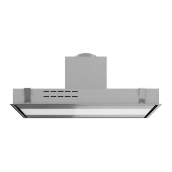
- Page 1 F u t u r o F u t u r o Skylight Designer range hood 54” version LIBRETTO ISTRUZIONI INSTRUCTIONS BOOKLET GEBRAUCHSANWEISUNG MODE D'EMPLOI MANUAL DE INSTRUCCIONES ИНСТРУКЦИИ INSTRUKCJA OBSŁUGI GEBRUIKSHANDLEIDING MANUAL DE INSTRUÇÕES BRUGSANIVSNINGER INSTRUKTIONSBOK OHJEKIRJA BRUKSANVISNING...
-
Page 2: Tools Needed
BLOWER LOCATION OPTION 1: Blower installed OPTION 2: Blower installed directly on hood in remote location (attic, garage, etc) Blower chamber may be installed with opening facing any direction 6" round, RIGID duct (do NOT use exible duct!) Duct Adapter (included) TOOLS NEEDED ø9 mm... - Page 3 BLOWER BOX DIMENSIONS 12" 6" 11" 5 1/2" 9 3/4" 11" 6" 12" 9 3/4" 11" 11" 4"...
- Page 4 DIMENSIONS IF BLOWER IS MOUNTED ON HOOD 3D OVERVIEW CUTOUT 23 1/4" DIMENSIONS 52 3/16" BOTTOM VIEW 11" SIDE VIEW 13 3/4" 10 3/4" 53 1/2" 11" SIDE VIEW 1/2" min 6" 1" max 5" 4" 24 5/8" 25 3/16" 22 3/4"...
- Page 5 DIMENSIONS IF BLOWER IS MOUNTED REMOTELY (ATTIC/GARAGE) 3D OVERVIEW CUTOUT 23 1/4" DIMENSIONS 52 3/16" BOTTOM VIEW SIDE VIEW 6" 5 1/4" 53 1/2" 1/2" min SIDE VIEW 1" max 5" 4" 24 5/8" 22 3/4" VIEW 51 9/16"...
- Page 6 INSTALLATION - BLOWER ON HOOD (x2) (x2)
- Page 7 INSTALLATION - BLOWER ON HOOD 150mm ø 15 Smontaggio! Disassembly! (x2) During installation, chains or cables may be used to TEMPORARILY support the hood. Permanent installation requires secure attachment to load-bearing elements (joists/frame/soft box) with screws or bolts. Fase Phase (x8)
- Page 8 INSTALLATION - REMOTE BLOWER 150mm (x2) Smontaggio! Disassembly!
- Page 9 INSTALLATION - REMOTE BLOWER During installation, chains or cables may be used to TEMPORARILY support the hood. Permanent installation requires secure attachment to load-bearing elements (joists, wooden frame, or soft box) using screws or bolts. Fase Phase...
- Page 10 FILTER & LIGHT BULB REMOVAL/REPLACEMENT MAGNETE - MAGNET...
-
Page 11: Safety Instructions And Warnings
SAFETY INSTRUCTIONS AND WARNINGS INTENDED USE • The equipment is solely intended to be used to extract fumes generated from cooking food in non-professional domestic kitchens : any other use is improper, can INSTALLATION WARNINGS cause damage to persons, things and pets and exempts the Manufacturer from any li- ability. - Page 12 Before connecting the equipment to the electrical mains power supply, check that: Phase page 8 • voltage supply corresponds with what is reported on the identiication plate located Check that the supplied laps (H) of the protection template (G) are bent on the opposite •...
- Page 13 REMOTE MOTOR UNIT Phase page 17 Open the perimeters uction panel (Fig. on page 20) and removet he metal ilters ( FM ) (Fig. The hood can be connected to the under-roof remote motor unit. page 20). Fasten the kit conveyor (CT) to the hood by means of 8 screws (V5) (Fig. In the case of an under-roof motor unit ( URS), it must be placed next to Connect the (CUE ) connector of the under-roof remote unit to the hood connector (CE) the technical compartment inside the home, protected against atmos-...
-
Page 14: Operation
OPERATION ASSOCIATING THE RADIO CONTROL WITH THE HOOD To save the new transmission code created in the hood, press the (timer) key on the push-button control panel of the hood for 2 seconds and, after the corresponding red LED WHEN SHOULD THE HOOD BE SWITCHED ON AND OFF? has lit up on the push-button control panel, press any key on the radio control within 10 Switch on the hood at least one minute before starting to cook: this enhances the airlow seconds. -
Page 15: Maintenance
USE OF THE ELECTRONIC PUSH BUTTON CONTROL PANEL CLEANING OF INTERNAL PARTS If required, the hood can be manually controlled by using the keyboard on the hood struc- It is forbidden to clean electrical parts, or parts related to the motor inside the ture.
Need help?
Do you have a question about the 54” Skylight and is the answer not in the manual?
Questions and answers