Maktec mt817 Technical Information
13mm 1/2"
Hide thumbs
Also See for mt817:
- Instruction manual (41 pages) ,
- Instruction manual (8 pages) ,
- Instruction manual (37 pages)
Advertisement
Quick Links
Download this manual
See also:
Instruction Manual
T
ECHNICAL INFORMATION
Model No.
Description
C
ONCEPT AND MAIN APPLICATIONS
Models MT817 and MT818 have been developed as the cosmetic
change of maktec hammer drills MT811 and MT812.
Their main features are:
• Industrial performance and durability at less expense
• Ergonomically designed handle with rubberized soft grip
The specification difference between these models are:
MT817/ 13mm (1/2") hammer drill with Keyed chuck
MT818/ 13mm (1/2") hammer drill with Keyless chuck
These models are also available with plastic carrying case
as "K" models; MT817K, MT818K
S
pecification
Voltage (V)
110
120
220
230
240
Specification
No load speed: min.
Impacts per min.: min.
Chuck type
Chuck capacity: mm (")
Capacities: mm (")
Variable speed control by trigger
Reverse switch
Protection against electric shock
Power supply cord: m (ft)
Weight according to
EPTA-Procedure 01/2003*: kg (lbs)
* with Side grip
S
tandard equipment
Chuck key S-13 ................................................ 1 (MT817 only)
Key holder 10 ................................................... 1 (MT817 only)
Side grip ........................................................... 1
Depth gauge ..................................................... 1 (for some countries)
Cap ................................................................... 1 (for some countries)
Plastic carrying case ........................................ 1 ("K models" only)
Note: The standard equipment for the tool shown above may vary by country.
O
ptional accessories
No
MT817, MT818
Hammer Drills 13mm (1/2")
Current (A)
Cycle (Hz)
4.1
3.8
2.1
2.0
1.9
Model No.
¹=rpm
ˉ
¹= ipm
ˉ
Steel
Wood
Concrete
Continuous Rating (W)
Input
50/60
430
50/60
---
50/60
430
50/60
430
50/60
430
MT817
Keyed
1.5 - 13 (1/16 - 1/2)
Double insulation
1.8 (3.9)
L
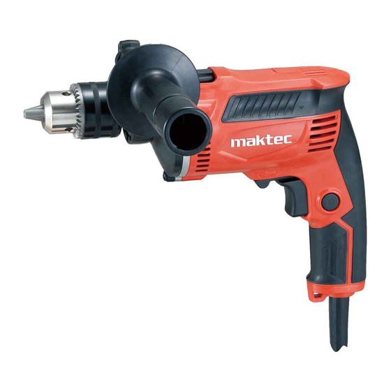
(The image above is MT817.)
Dimensions: mm ( " )
Model No.
MT817
Length (L)
255 (10)
Width (W)
72 (2-13/16)
Height (H)
193 (7-5/8)
Output
220
220
220
220
220
MT818
0 - 2,800
0 - 30,800
Keyless
13 (1/2)
18 (11/16)
13 (1/2)
Yes
Yes
2.0 (6.6)
1.7 (3.7)
PRODUCT
P 1/ 10
H
W
MT818
258 (10-1/8)
Max. Output (W)
340
340
340
340
340
Advertisement

Related Manuals for Maktec mt817


Summary of Contents for Maktec mt817
- Page 1 MT817, MT818 Description Hammer Drills 13mm (1/2") ONCEPT AND MAIN APPLICATIONS Models MT817 and MT818 have been developed as the cosmetic change of maktec hammer drills MT811 and MT812. Their main features are: • Industrial performance and durability at less expense •...
-
Page 2: Necessary Repairing Tools
P 2/ 10 epair CAUTION: Repair the machine in accordance with “Instruction manual” or “Safety instructions”. [1] NECESSARY REPAIRING TOOLS Code No. Description Use for 1R004 Retaining ring pliers ST-2 removing Retaining ring WR12 from Spindle 1R005 Retaining ring pliers RT-2N removing Retaining ring R-32 from Gear housing 1R026 Bearing setting pipe 16-8.2... - Page 3 P 3/ 10 epair [3] DISASSEMBLY/ASSEMBLY [3] DISASSEMBLY/ASSEMBLY [3] -1. Armature [3] -1. Armature DISASSEMBLING DISASSEMBLING (1) Disassemble Armature from the machine as drawn in Fig. 2. Fig. 2 2. Remove three 5x25 Tapping screws. 2. Remove three 5x25 Tapping screws. 1.
- Page 4 P 4/ 10 epair [3] DISASSEMBLY/ASSEMBLY [3] -1. Armature (cont.) DISASSEMBLING (2) Remove Ball bearings from Armature shaft as drawn in Fig. 3. Fig. 3 2. The claws of 1R269 cannot hold Ball bearing 607ZZ firmly because of 1. Remove Ball bearing 608DDW the small gap between the bearing and insulation washer.
- Page 5 P 5/ 10 epair [3] DISASSEMBLY/ASSEMBLY [3] -3. Helical Gear 37 and Ball bearing 6002DDW DISASSEMBLING (1) Remove Drill chuck as drawn in Figs. 4 and 5. (2) Separate Gear housing from Motor housing. And remove Armature from Cam housing complete as drawn in Fig.
- Page 6 P 6/ 10 epair [3] DISASSEMBLY/ASSEMBLY [3] -3. Helical Gear 37 and Ball bearing 6002DDW (cont.) DISASSEMBLING (4) Remove Ball bearing 6002DDW as drawn in Fig. 7. Fig. 7 1. Remove Retaining 2. Insert Spindle into Ball 3. Strike the head of the re-inserted Spindle ring R-32 with 1R005.
- Page 7 P 7/ 10 epair [3] DISASSEMBLY/ASSEMBLY [3] -4. Cam Housing Compete DISASSEMBLING (1) Remove Drill chuck as drawn in Figs. 4 and 5. (2) Separate Gear housing from Motor housing. And remove Armature from Cam housing complete as drawn in Fig. 2. (3) Separate Cam housing complete from Gear housing.
-
Page 8: Circuit Diagram
P 8/ 10 ircuit diagram Fig. D-1 Color index of lead wires' sheath Black Orange Blue Purple Brown White Brush holder A Chike coil Field Brush holder B Earth terminal (It depends on Chike coil specifications.) Switch 2a 2 2b Noise suppressor Power supply cord... -
Page 9: Wiring Diagram
P 9/ 10 iring diagram Fig. D-2 Wiring of Field lead wire Route Field lead wire (white) Rib A between Rib A and Rib B. Route Field lead wire (white) through the groove. Rib B Rib C Route Field lead wire (black) between Rib C and Rib D. - Page 10 P 10/ 10 iring diagram Fig. D-4 Wiring in Handle section Put Choke coil (orange) between Rib F and Rib G. Rib F Choke coil (orange) Rib G Do not route the earth lead wire (white) over Brush holders the top of the cables when routing the lead wires through Lead wire holders.
Need help?
Do you have a question about the mt817 and is the answer not in the manual?
Questions and answers