Maktec MT814 Technical Information
Hammer drills 16mm (5/8")
Hide thumbs
Also See for MT814:
- Instruction manual (44 pages) ,
- Instruction manual (36 pages) ,
- Instruction manual (8 pages)
Table of Contents
Advertisement
Quick Links
Download this manual
See also:
Instruction Manual
T
ECHNICAL INFORMATION
Model No.
Description
C
ONCEPT AND MAIN APPLICATIONS
Models MT814 and MT815 have been developed as the aesthetic
change models of maktec hammer drill MT813, featuring:
Industrial performance and durability at less expense
Tool body ergonomically designed to;
provide comfortable grip and more control.
give maximum power thrust.
The specification difference between MT814 and MT815 is;
MT814: Keyed chuck model
MT815: Keyless chuck model
These models will be also available with:
Plastic carrying case as "K models" (MT814K, MT815K)
Tool box as "KSP models" (MT814KSP, MT815KSP)
S
pecification
Voltage (V)
110
120
220
230
240
Model No.
No load speed: min
Impacts per min.: min
Chuck type
Chuck capacity: mm (")
Capacities: mm (")
Variable speed control by trigger
Reverse switch
Protection against electric shock
Power supply cord: m (ft)
Weight according to
EPTA-Procedure 01/2003*: kg (lbs)
* including Side grip
S
tandard equipment
Chuck key S-13 ................................................ 1 pc (MT814 only)
Key holder 10 ................................................... 1 pc (MT814 only)
Side grip ........................................................... 1 pc
Depth gauge ..................................................... 1 pc
Plastic carrying case ........................................ 1 pc ("K models" only)
Tool box ........................................................... 1 pc ("KSP models" only)
Note: The standard equipment for the tool shown above may vary by country.
O
ptional accessories
TCT drill bits, etc.
MT814, MT815
Hammer Drills 16mm (5/8")
Current (A)
Cycle (Hz)
6.8
50/60
6.2
50/60
3.4
50/60
3.3
50/60
3.1
50/60
= rpm
-1
= ipm
-1
Concrete
Steel
Wood
Model No.
Length (L)
Width (W)
Height (H)
Continuous Rating (W)
Input
710
---
710
710
710
MT814
0 - 3,200
0 - 48,000
Keyed
1.5 - 13 (1/16 - 1/2)
16 (5/8)
13 (1/2)
30 (1-3/16)
Yes
Yes
Double insulation
2.0 (6.6)
2.1 (4.6)
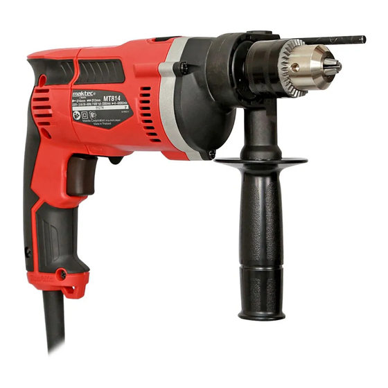
PRODUCT
L
W
(The image above is
Dimensions: mm ( " )
MT814
296 (11-5/8)
295 (11-5/8)
77 (3)
202 (8)
Max. Output (W)
Output
420
630
420
630
420
630
420
630
420
630
MT815
Keyless
2.0 (4.4)
P 1/ 8
H
MT815.)
MT815
Advertisement
Table of Contents

Related Manuals for Maktec MT814


Summary of Contents for Maktec MT814
- Page 1 MT814, MT815 Description Hammer Drills 16mm (5/8") ONCEPT AND MAIN APPLICATIONS Models MT814 and MT815 have been developed as the aesthetic change models of maktec hammer drill MT813, featuring: Industrial performance and durability at less expense Tool body ergonomically designed to;...
- Page 2 P 2/ 8 epair CAUTION: Repair the machine in accordance with “Instruction manual” or “Safety instructions”. [1] NECESSARY REPAIRING TOOLS Code No. Description Use for 1R005 Description Removing / Fitting Retaining ring R-35 1R026 Bearing setting pipe 16-8.2 Removing Helical gear 37 1R028 Bearing setting pipe 20-12.2 Assembling Helical gear 37 to Spindle...
- Page 3 Fig. 2 1. Fit the flats of Spindle to the notch of 1R139 and then hold 1R139 in vise. 2. Attach 1R224 and 1R298 to 1R223 and then secure 1R298 with Drill chuck. 3. Turn 1R223 counterclockwise. MT814 MT815 1R223 1R298...
- Page 4 P 4/ 8 epair [3] DISASSEMBLY/ASSEMBLY [3]-2. Armature DISASSEMBLING (1) Remove Armature from the machine as illustrated in Fig. 3. Fig. 3 1. Remove Handle cover complete 2. Separate Gear housing and Gear 3. Armature ass’y can be removed and four 4x18 Tapping screws. housing cover complete from together with Gear housing cover Remove Carbon brushes together...
- Page 5 P 5/ 8 epair [3] DISASSEMBLY/ASSEMBLY [3]-3. Helical gear 37, Ball bearing 6202DDW DISASSEMBLING (1) Remove Drill chuck as illustrated in Fig. 2. (2) Separating Gear housing, remove Pin 4, Steel ball 3.5 and Rind spring 12 from Spindle as illustrated in Fig. 5. Fig.
- Page 6 P 6/ 8 epair [3] DISASSEMBLY/ASSEMBLY [3]-3. Helical gear 37, Ball bearing 6202DDW (cont.) ASSEMBLING (4) Remove Ball bearing 6202DDW as illustrated in Fig. 7. Use the removed Spindle as a jig. Fig. 7 2. Strike Spindle with Plastic hammer, and Ball bearing 6202DDW 1.
- Page 7 P 7/ 8 ircuit diagram Fig. D-1 Color index of lead wires' sheath Black Orange Blue Brown Purple Brush holder on the opposite of Switch Field viewed from Commutator side Brush holder near Switch Switch Noise suppressor (if used) Black Lead wire is used White Lead wire is used for some countries.
- Page 8 P 8/ 8 iring diagram Fig. D-2 Wiring of Field lead wires Left coil Route Field lead wires (black, white) of Left coil between Rib A and Rib B of Motor housing. Right coil (Handle cover side) Route Field lead wires (black, red) Rib A of Right coil between Rib B and Rib C of Motor housing.
Need help?
Do you have a question about the MT814 and is the answer not in the manual?
Questions and answers