Advertisement
Quick Links
T
ECHNICAL INFORMATION
Models No.
Description
C
ONCEPT AND MAIN APPLICATIONS
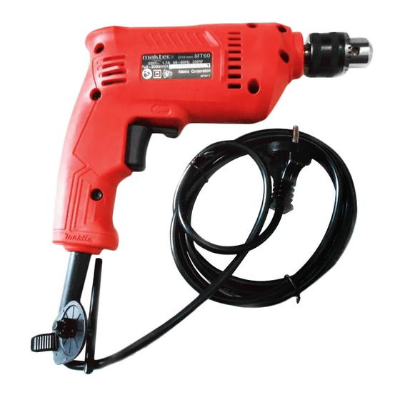
Model MT60 has been developed as a maktec brand 10mm Drill
for emerging countries such as China and India by prioritizing
cost competitiveness.
Because this model has been designed through partial re-standardization
of product performance to meet the requirements of the target market,
its formulation of maktec design and model number has been changed
to distinguish this model from the current maktec series models.
S
pecification
Voltage (V)
220
230 - 240
No load speed: min-
Drill chuck type
Chuck capacity: mm (")
Capacities: mm (") Steel
Reverse switch
Variable speed control by trigger
Protection against electric shock
Power supply cord: m (ft)
Weight according to
EPTA-Procedure 01/2003: kg (lbs)
S
tandard equipment
Chuck key .......................... 1
Note: The standard equipment for the tool shown above may vary by country.
MT60
10mm Drill
Current (A)
Cycle (Hz)
1.7
50/ 60
1.6
50/ 60
= rpm
1
Wood
Continuous Rating (W)
Input
350
350
0 - 3,000
Keyed
1.5 - 10 (1/16 - 3/8)
10 (3/8)
20 (13/16)
Yes
Yes
Double insulation
2.0 (6.6)
1.2 (2.6)
PRODUCT
L
W
Dimensions: mm (")
Length (L)
Width (W)
Height (H)
Max. Output (W)
Output
170
300
170
300
P 1/ 8
H
230 (9)
66 (2-5/8)
176 (6-15/16)
Advertisement

Related Manuals for Maktec MT60


Summary of Contents for Maktec MT60
- Page 1 Models No. Description 10mm Drill ONCEPT AND MAIN APPLICATIONS Model MT60 has been developed as a maktec brand 10mm Drill for emerging countries such as China and India by prioritizing cost competitiveness. Because this model has been designed through partial re-standardization...
- Page 2 P 2/ 8 epair CAUTION: Repair the machine in accordance with “Instruction manual” or “Safety instructions”. [1] NECESSARY REPAIR TOOLS Code No. Description Use for 1R004 Retaining Ring S Pliers ST-2 removing/ assembling Ring spring 11 from Spindle 1R032 Bearing Setting Plate 8.2 removing Helical gear 35 1R232 Pipe 30...
-
Page 3: Drill Chuck
P 3/ 8 epair [3] DISASSEMBLY/ASSEMBLY [3]-1. Drill Chuck ASSEMBLING Do the reverse of the disassembling steps. [3]-2. Spindle and Helical Gear 35 DISASSEMBLING (1) Remove Drill chuck. (Fig. 2) (2) Remove Spindle section from Housing (L), then disassemble Spindle from Helical gear 35. (Fig. 3) Fig. - Page 4 P 4/ 8 epair [3] DISASSEMBLY/ASSEMBLY [3]-2. Spindle and Helical Gear 35 DISASSEMBLING (3) Remove Ball bearing 6001ZZ as illustrated in Fig. 4. Fig. 4 7. Remove Ring spring 11 with 1R004. 8. Remove Ball bearing 6001ZZ with 1R269. Ring spring 11 1R004 Ball bearing Spindle...
-
Page 5: Circuit Diagram
P 5/ 8 ircuit diagram For the Market where Radio Interference Suppression is required Color index of lead wires' sheath Choke coil (purple) Black White BH A Orange Purple Field viewed from Commutator end [Housing L side] [Housing R side] BH B Trigger F/R Change... - Page 6 P 6/ 8 ircuit diagram For the Market where Radio Interference Suppression is required Wiring to Brush Holder Housing L side For easy wiring, set Brush holders on Housing L as instructed below: *Brush holder on Switch side - Face the window of Brush holder towards Housing R side.
- Page 7 P 7/ 8 ircuit diagram For the Market where Radio Interference Suppression is not required Color index of lead wires' sheath Black White BH A Orange Purple Field viewed from Commutator end [Housing L side] [Housing R side] BH B Trigger F/R Change lever...
- Page 8 P 8/ 8 ircuit diagram For the Market where Radio Interference Suppression is not required Wiring to Brush Holder Housing L side For easy wiring, set Brush holders on Housing L as instructed below: *Brush holder on Switch side - Face the window of Brush holder towards Housing R side.
Need help?
Do you have a question about the MT60 and is the answer not in the manual?
Questions and answers