
Related Manuals for BIRD 8141


Summary of Contents for BIRD 8141
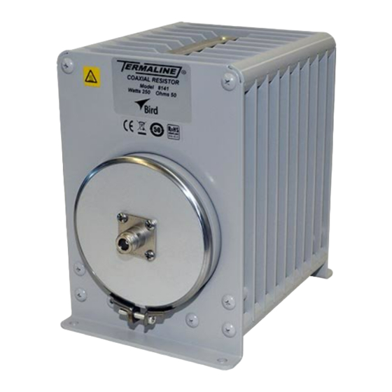
- Page 1 Termaline ® Load Resistor Operation Manual Model 8141 ©Copyright 2016 by Bird Electronic Corporation Instruction Book Part Number 920-8141 Rev. D Termaline is a trademark of Bird Electronic Corporation...
-
Page 2: Safety Precautions
Safety Precautions The following are general safety precautions that are not necessarily related to any specific part or procedure, and do not necessarily appear elsewhere in this publication. These precautions must be thoroughly understood and apply to all phases of operation and maintenance. WARNING Keep Away From Live Circuits Operating Personnel must at all times observe general safety precautions. -
Page 3: Safety Symbols
This product contains substrate made of beryllium oxide. This is a potentially toxic ceramic and may be harmful to health. Beryllia oxide must be disposed of in accordance with the legal statutes dealing with hazardous material. Do not attempt to repair this unit, but return to BIRD ELECTRONIC CORPORATION. See page... -
Page 4: Safety Statements
Termaline® Coaxial Load Resistor Safety Statements USAGE ANY USE OF THIS INSTRUMENT IN A MANNER NOT SPECIFIED BY THE MANUFACTURER MAY IMPAIR THE INSTRUMENT’S SAFETY PROTECTION. EL USO DE ESTE INSTRUMENTO DE MANERA NO ESPECIFICADA POR EL FABRICANTE, PUEDE ANULAR LA PROTECCIÓN DE SEGURIDAD DEL INSTRUMENTO. - Page 5 Safety Precautions SERVICE SERVICING INSTRUCTIONS ARE FOR USE BY SERVICE - TRAINED PERSONNEL ONLY. TO AVOID DANGEROUS ELECTRIC SHOCK, DO NOT PERFORM ANY SERVICING UNLESS QUALIFIED TO DO SO. SERVICIO LAS INSTRUCCIONES DE SERVICIO SON PARA USO EXCLUSIVO DEL PERSONAL DE SERVICIO CAPACITADO. PARA EVITAR EL PELIGRO DE DESCARGAS ELÉCTRICAS, NO REALICE NINGÚN SERVICIO A MENOS QUE ESTÉ...
-
Page 6: About This Manual
Termaline® Coaxial Load Resistor About This Manual This manual covers the operating and maintenance instructions for the following models: 8141 8141-010 Changes to this Manual We have made every effort to ensure this manual is accurate. If you discover any errors, or if you have suggestions for improving this manual, please send your comments to our Solon, Ohio factory. -
Page 7: Table Of Contents
Table of Contents Safety Precautions ......... i Safety Symbols . - Page 8 Termaline® Coaxial Load Resistor Chapter 5 Maintenance ........7 Troubleshooting .
-
Page 9: Chapter 1 Introduction
Chapter 1 Introduction General This instruction book is intended for use by operators of the Models 8141 and 8141-010 Termaline Load Resistor. This chapter contains introductory information including product specifications; items supplied; and accessory items. Purpose And Function The Models 8141 and 8141-010 Termaline Load Resistor are portable, general purpose 50 ohm coaxial transmission line terminations. -
Page 10: Power And Utility Requirements
Termaline® Coaxial Load Resistor Power and Utility Requirements Other than the RF power input the Models 8141 and 8141-010 has no need for an external source of power or utility services. Environmental Requirements The loads should be operated in as clean and vibration free an environment as possible. -
Page 11: Chapter 2 Theory Of Operation
Chapter 2 Theory of Operation General The Models 8141 and 8141-010 Termaline Load Resistor consists essentially of a cylindrical film type resistor immersed in a dielectric coolant. The resistor, individually selected for its accuracy, is enclosed in a special tapered housing which provides a linear reduction in surge impedance directly proportional to the distance along the resistor. -
Page 12: Chapter 3 Installation
No. 12 wood screws if desired. The four 9/32 inch holes in the mounting brackets form a base rectangle of 7-15/32" x 5-1/8" (189.7 x 130.2 mm) for the Model 8141 and 7/13/32. x 5/1/8. (180 x 130.2 mm) for the Model 8141-010. -
Page 13: Chapter 4 Operating Instructions
Operating Instructions Start-up Connect the Models 8141 and 8141-010 Termaline Load Resistor to the transmitting equipment under test with 50 ohm coaxial cable such as RG-213/U or equal, equipped with a Male N type plug (UG-21E/U or equal) which mates with the RF input connector of the load. -
Page 14: Emergency Shutdown
Termaline® Coaxial Load Resistor Emergency Shutdown WARNING Never attempt to disconnect RF equipment from the transmission line while RF power is being applied. Leaking RF energy is a potential health hazard. Turn off the equipment by removing power from the RF generator. -
Page 15: Chapter 5 Maintenance
Chapter 5 Maintenance Troubleshooting For corrections requiring repair or replacement of components, refer to the appropriate section for each specific model. PROBLEM POSSIBLE CAUSE REMEDY Tighten slightly with Clamping bands not tight. screwdriver. Coolant oil leak around clamping band or radiator. Faulty O-Ring (front). -
Page 16: Cleaning
Termaline® Coaxial Load Resistor Cleaning Outside Surface The outside surface of the instrument, especially the cooling fins, should be wiped free of dust and dirt when necessary. Clean the RF input connector with a clean dry cloth. Use an aerosol type non residue forming contact cleaner on the inaccessible portions. -
Page 17: Disassembly
3. Remove the diaphragm cover and lift the diaphragm from the back end of the radiator tank. Note: The diaphragm should be soft and pliable. If it is hard or shows signs of surface cracks, replace it. (Bird P/N 2430-015). -
Page 18: Rf Load Resistor Assembly
Note: Hold for a short time over tank to allow oil to drain back in. 5. Inspect the O-Ring seal just inside the sloped flange of the mounting ring. 6. Replace the seal, Bird P/N 5-230, if it shows any evidence of cuts or deterioration such as hardening or surface cracks. -
Page 19: Rf Load Resistor Assembly
Beryllia oxide must be disposed of in accordance with the legal statutes dealing with hazardous material. Do not attempt to repair this unit, but return to BIRD ELECTRONIC CORPORATION. Repairs beyond what is covered in this instruction book will require return of the equipment to Bird Electronic Corporation for service. -
Page 20: Shipment
Horizontal only Finish Grey Powder Coat Paint Replacement Parts List Item Description Part Number Radiator assembly 2440-015 RF section assembly 8141-002 Coolant .35 gallons 5-1070-2 (1.3 liter)(1 gallon container) “QC” connector See Table Below. Clamp band assembly 2430-055 O-Ring seal 5-230... - Page 21 Maintenance Available QC Type Connectors Description Part Number N-Female 4240-062 N-Male 4240-063 HN-Female 4240-268 HN-Male 4240-278 LC-Female 4240-031 LC-Male 4240-025 LT-Female 4240-018 LT-Male 4240-012 C-Female 4240-100 C-Male 4240-110 UHF-Female (SO-230 4240-050 UHF-Male (PL-259) 4240-179 7/8" EIA Air Line 4240-002...
-
Page 22: Limited Warranty
Limited Warranty All products manufactured by Seller are warranted to be free from defects in material and workmanship for a period of one (1) year, unless otherwise specified, from date of shipment and to conform to applicable specifications, drawings, blueprints and/or samples. Seller’s sole obligation under these warranties shall be to issue credit, repair or replace any item or part thereof which is proved to be other than as warranted;...
Need help?
Do you have a question about the 8141 and is the answer not in the manual?
Questions and answers