BIRD Termaline 8920 Series Operation Manual
Load resistor
Hide thumbs
Also See for Termaline 8920 Series:
- Operation manual (32 pages) ,
- Instruction book (30 pages) ,
- Manual (30 pages)
Table of Contents
Advertisement
Quick Links
®
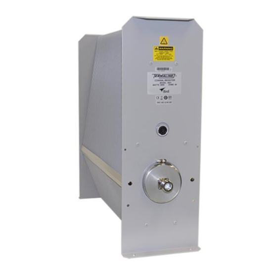
Termaline
Load Resistor
Series 8920
Operation Manual
This unit requires the supplied vent plug be installed prior to use.
Operating the unit without the vent plug installed WILL result in equipment damage and may
cause personal injury.
©Copyright 2023 by Bird Technologies, Inc.
Instruction Book Part Number 920-8920S Rev. J
Termaline® and Thruline® are Registered Trademarks
of Bird Electronic Corporation
Advertisement
Table of Contents

Related Manuals for BIRD Termaline 8920 Series


Summary of Contents for BIRD Termaline 8920 Series
- Page 1 This unit requires the supplied vent plug be installed prior to use. Operating the unit without the vent plug installed WILL result in equipment damage and may cause personal injury. ©Copyright 2023 by Bird Technologies, Inc. Instruction Book Part Number 920-8920S Rev. J Termaline® and Thruline® are Registered Trademarks...
- Page 3 Safety Precautions Safety Precautions The following are general safety precautions that are not necessarily related to any specific part or procedure, and do not necessarily appear elsewhere in this publication. These precautions must be thoroughly understood and apply to all phases of operation and maintenance. Keep Away From Live Circuits Operating Personnel must at all times observe general safety precautions.
-
Page 4: Safety Symbols
Termaline® Load Resistor Safety Symbols Warnings call attention to a procedure, which if not correctly performed, could result in personal injury. Cautions call attention to a procedure, which if not correctly performed, could result in damage to the instrument. This symbol indicates that a shock hazard exists if the precautions in the instruction manual are not followed. -
Page 5: Warning Statements
Safety Precautions Warning Statements The following safety warnings appear in the text where there is danger to operating and maintenance personnel, and are repeated here for emphasis. The load weighs 119 lb. (54 kg), do not attempt to lift alone. Two or more people, or mechanical assistance, are required to lift the load. -
Page 6: Caution Statements
If installed, connect optional interlock before applying RF power. See page 6 Use only Bird coolant, P/N 5-1070, to prevent damage to the load. See page 12. Blocking should be used to support the load to avoid damage to the interlock thermoswitch. -
Page 7: Safety Statements
Safety Precautions Safety Statements USAGE ANY USE OF THIS INSTRUMENT IN A MANNER NOT SPECIFIED BY THE MANUFACTURER MAY IMPAIR THE INSTRUMENT’S SAFETY PROTECTION. EL USO DE ESTE INSTRUMENTO DE MANERA NO ESPECIFICADA POR EL FABRICANTE, PUEDE ANULAR LA PROTECCIÓN DE SEGURIDAD DEL INSTRUMENTO. BENUTZUNG WIRD DAS GERÄT AUF ANDERE WEISE VERWENDET ALS VOM HERSTELLER BESCHRIEBEN, KANN DIE GERÄTESICHERHEIT BEEINTRÄCHTIGT WERDEN. - Page 8 Termaline® Load Resistor SERVICE SERVICING INSTRUCTIONS ARE FOR USE BY SERVICE - TRAINED PERSONNEL ONLY. TO AVOID DANGEROUS ELECTRIC SHOCK, DO NOT PERFORM ANY SERVICING UNLESS QUALIFIED TO DO SERVICIO LAS INSTRUCCIONES DE SERVICIO SON PARA USO EXCLUSIVO DEL PERSONAL DE SERVICIO CAPACITADO.
- Page 9 Safety Precautions CONNECT INTERLOCK TO TRANSMITTER/GENERATOR/AMPLIFIER BEFORE OPERATING. BRANCHER LE VERROUILLAGE À L’ÉMETTEUR/GÉNÉRATEUR/AMPLIFICATEUR AVANT EMPLOI. CONECTE EL INTERBLOQUEO AL TRANSMISOR/GENERADOR/AMPLIFICADOR ANTES DE LA OPERACION. VOR INBETRIEBNAHME VERRIEGELUNG AM SENDER/GENERATOR/VERSTÄRKER ANSCHLIESSEN. PRIMA DI METTERE IN FUNZIONE L’APPARECCHIO, COLLEGARE IL DISPOSITIVO DI BLOCCO AL TRASMETTITORE/GENERATORE/AMPLIFICATORE.
-
Page 10: About This Manual
When inquiring about updates to this manual refer to the part number and revision on the title page. Chapter Layout Introduction — Describes the features of the Bird Termaline RF Load Resistor lists equipment supplied and optional equipment, and provides power-up instructions. Theory of Operation —... -
Page 11: Table Of Contents
Table of Contents Safety Precautions ..............i Safety Symbols . - Page 12 Termaline® Load Resistor Shipping the Load ................15 Customer Service .
-
Page 13: Chapter 1 Introduction
Bird 8920 Series Loads are portable, 50 ohm, coaxial RF transmission line terminations, designed for frequency ranges of DC – 1 GHz. Bird 8920D Series Loads are identical, except that they are designed for the UHF (470 – 860 MHz) band. They provide accurate, dependable, and low reflection line terminations. Up to 5000 watts of RF power can be dissipated. -
Page 14: Chapter 2 Theory Of Operation
Theory of Operation Load Resistor Bird 8920 series loads consist of a thin-film-on-ceramic resistor immersed in a dielectric coolant. The resistor, individually selected for its accuracy, is enclosed in a special housing. When surrounded by the coolant, this produces a uniform, practically reflectionless line termination over the specified frequencies. -
Page 15: Chapter 3 Installation
If the shipping container is not damaged, unpack the unit. Save shipping materials for repackaging. 2. Inspect unit for visual signs of damage. If there is damage, immediately notify the shipping carrier and Bird Technologies. Site and Shelter Requirements The unit should be operated in a dry, dust and vibration free environment. -
Page 16: Mounting
Termaline® Load Resistor Mounting This load is designed for operation in a horizontal position only, with the mounting brackets down.Operation in any other orientation will cause insufficient cooling of the unit leading to premature failure. The load is equipped for either portable use or fixed installation. The mounting brackets on the front and rear faces have four mounting slots arranged in a 4 ... -
Page 17: Thermoswitch
Connector - P/N 2450-018 Installing Thermoswitch Bird 8920 series loads can be equipped with an optional interlock thermoswitch, P/N 8890-008. It is normally closed, opening at 236 °C (457 °F), with a rating of 10A @ 120 VAC and 5A @ 230 VAC. -
Page 18: Interlock Connection
Termaline® Load Resistor Figure 2 Socket Plug Do not contaminate the coolant with pipe sealant. 6. Sparingly apply pipe sealing compound to the external threads of the thermoswitch only. 7. Install the thermoswitch in place of the plug. Torque to 40 +/-2 ft-lbs. 8. -
Page 19: Connecting Rf Power
Installation The ring-nut (A) must be in place over the base plug (D) with the knurled end facing out. 7. Screw on the cover ring (C). 8. Fasten the cable clamp (E) in place. 9. Tighten both yoke screws (H). 10. - Page 20 Termaline® Load Resistor “QC” Connector Coupling Use 50 ohm coaxial cable such as RG-218/U or -220/U (-17A or -19A), appropriate for the frequency and power level of operation. Use a cable connector which will mate with the one on the load. Swivel Flanged Coupling To couple the swivel flange with a flanged RF transmission line, use an appropriate coupling kit.
-
Page 21: Chapter 4 Operating Instructions
"Vent Plug" on page 4 Normal Operation Bird 8920 series loads have no indicators or operating controls. They require no special operating procedures or surveillance when their performance limits are not exceeded. Follow the instructions for the specific transmitter equipment. -
Page 22: Chapter 5 Maintenance
Chapter 5 Maintenance This chapter covers cleaning, inspection, trouble-shooting, and specifications for the Bird 8920 series loads. Never attempt to connect or disconnect RF equipment from the transmission line while RF power is being applied. Leaking RF energy is a potential health hazard. -
Page 23: Routine Maintenance
Maintenance Routine Maintenance shows the location of components which may be referred to in this section. Figure 6 Figure 6 Maintenance and Repair Locations Clean the Load The outside surface of the instrument should be wiped free of dust and dirt when necessary. ... -
Page 24: Inspect The Coolant
Oil is slippery. If a leak occurs, be careful not to fall. Correct any coolant leakage before inspection. (See "Troubleshooting" on page 10 To inspect the coolant: Use only Bird coolant, P/N 5-1070, to prevent damage to the load. 1. Remove the load resistor (See "Load Resistor" on page 14 ... -
Page 25: Repair
Replace RF Connector The Model 8921, only, has a special Bird “QC” connector which allows easy changing of the RF connector. This does not disturb the coolant seal or affect the electrical continuity of the load. To change the connector, proceed as follows: 1. -
Page 26: Load Resistor
Termaline® Load Resistor 5. Replace the screws. If not using the connector normally supplied, frequency and power must be limited to the capabilities of the connector. Load Resistor Oil is slippery. If a leak occurs, be careful not to fall. To change the load resistor assembly: 1. -
Page 27: Storage And Shipment
Maintenance The vent plug must be installed at all times when the unit is in operation or cooling. Always check to ensure vent plug is installed prior to operation. Failure to do so WILL result in damage to the equipment and endanger the operator’s safety. 14. -
Page 28: Customer Service
Any maintenance or service procedure beyond the scope of those in this chapter should be referred to a qualified service center. If the unit needs to be returned for any reason, request an Return Material Authorization (RMA) through the Bird Technologies website. All instruments returned must be shipped prepaid and to the attention of the RMA number. -
Page 29: Specifications
Maintenance Specifications Frequency Range 8922D, 8926D, 8927D 470 – 860 MHz All other models DC – 1 GHz Power Rating 5000 W continuous duty Peak Power for Pulse Width 1 µs 150 kW 10 µs 115 kW 100 µs 80 kW 1000 µs 54 kW 5000 µs... -
Page 30: Replacement Parts
Termaline® Load Resistor Replacement Parts Description Part Number RF Load Resistor: 8921 8890A050 8922, 8922D 8892-015 8926 8891-050 8926D 8891-071 8927 8897-003 8927D 8897-006 8928 8898-006 Resistor O-Ring 5-230 Clamping Band Assembly 2430-055 Plug Vent 2450-094 Shipping 2450-049 Interlock Thermoswitch 8890-008 Thermoswitch Body 8890-005... -
Page 31: Available "Qc" Type Connectors
Maintenance Available “QC” Type Connectors Connector Part Number BNC-Female 4240-125 BNC-Male 4240-132 C-Female 4240-100 C-Male 4240-110 HN-Female 4240-268 HN-Male 4240-278 LC-Female 4240-031 LC-Male 4240-025 Open Term. 4240-080 # 10-32 Nut LT-Female 4240-018 LT-Male 4240-012 N-Female 4240-062 N-Male 4240-063 SC-Female 4240-090 SMA-Female 4240-336 SMA-Male... -
Page 32: Limited Warranty
Limited Warranty All products manufactured by Seller are warranted to be free from defects in material and workmanship for a period of one (1) year, unless otherwise specified, from date of shipment and to conform to applicable specifications, drawings, blueprints and/or samples. Seller’s sole obligation under these warranties shall be to issue credit, repair or replace any item or part thereof which is proved to be other than as warranted;...
Need help?
Do you have a question about the Termaline 8920 Series and is the answer not in the manual?
Questions and answers