
Related Manuals for BIRD 8135


Summary of Contents for BIRD 8135
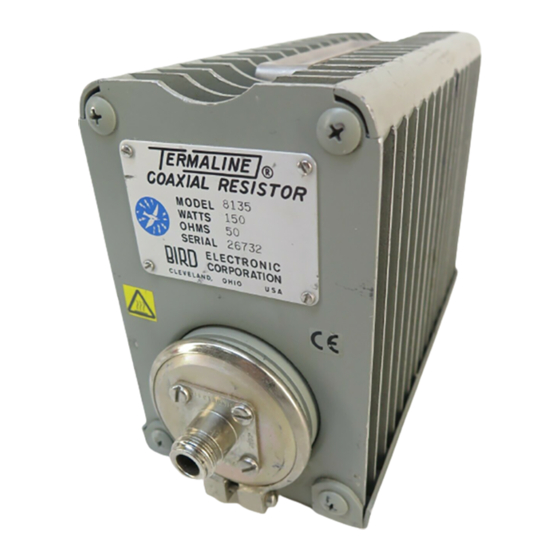
- Page 1 Termaline Coaxial ® Load Resistor Operation Manual Model 8135 ©Copyright 2016 by Bird Electronic Corporation Instruction Book Part Number 920-8135 Rev. D Termaline is a trademark of Bird Electronic Corporation...
-
Page 2: Safety Precautions
Safety Precautions The following are general safety precautions that are not necessarily related to any specific part or procedure, and do not necessarily appear elsewhere in this publication. These precautions must be thoroughly understood and apply to all phases of operation and maintenance. WARNING Keep Away From Live Circuits Operating Personnel must at all times observe general safety precautions. -
Page 3: Safety Symbols
Safety Precautions Safety Symbols WARNING Warning notes call attention to a procedure, which if not correctly performed, could result in personal injury. CAUTION Caution notes call attention to a procedure, which if not correctly performed, could result in damage to the instrument. Note: Calls attention to supplemental information. -
Page 4: Safety Statements
Termaline® Coaxial Load Resistor Safety Statements USAGE ANY USE OF THIS INSTRUMENT IN A MANNER NOT SPECIFIED BY THE MANUFACTURER MAY IMPAIR THE INSTRUMENT’S SAFETY PROTECTION. EL USO DE ESTE INSTRUMENTO DE MANERA NO ESPECIFICADA POR EL FABRICANTE, PUEDE ANULAR LA PROTECCIÓN DE SEGURIDAD DEL INSTRUMENTO. - Page 5 Safety Precautions SERVICE SERVICING INSTRUCTIONS ARE FOR USE BY SERVICE - TRAINED PERSONNEL ONLY. TO AVOID DANGEROUS ELECTRIC SHOCK, DO NOT PERFORM ANY SERVICING UNLESS QUALIFIED TO DO SO. SERVICIO LAS INSTRUCCIONES DE SERVICIO SON PARA USO EXCLUSIVO DEL PERSONAL DE SERVICIO CAPACITADO. PARA EVITAR EL PELIGRO DE DESCARGAS ELÉCTRICAS, NO REALICE NINGÚN SERVICIO A MENOS QUE ESTÉ...
-
Page 6: About This Manual
About This Manual This manual covers the operating and maintenance instructions for the following models: 8135 Changes to this Manual We have made every effort to ensure this manual is accurate. If you discover any errors, or if you have suggestions for improving this manual, please send your comments to our Solon, Ohio factory. -
Page 7: Table Of Contents
Table of Contents Safety Precautions ......... i Safety Symbols . - Page 8 Termaline® Coaxial Load Resistor Normal Operation ..........5 Operation Under Abnormal Conditions .
-
Page 9: Chapter 1 Introduction
1.3 to 1.0 maximum from 2000 to 4000 MHz. Dimensions and Weight The Model 8135 is 8-13/16 inches long, 4 inches wide, and 6-7/16 inches high (224 x 102 x 164 mm). It has a weight of 6 lb (2.7 kg) net and a shipping weight of 8 lb (3.6 kg). -
Page 10: Items Furnished
The RF input connector, located on the front face of the unit, is a Female N. It is a special “Quick-Change” design permitting rapid and easy interchange with other Bird AN type “QC” connectors. This instruction book is the only other item provided. -
Page 11: Chapter 2 Theory Of Operation
Chapter 2 Theory of Operation General The Model 8135 Termaline Load consists essentially of a cylindrical film type resistor immersed in dielectric coolant. The resistor, individually selected for its accuracy, is enclosed in a special tapered housing which provides a linear reduction in surge impedance directly proportional to the distance along the load resistor. -
Page 12: Chapter 3 Installation
Free air circulation around the Model 8135 Termaline Load is essential. Keep the load in the clear, and do not place it near heated surfaces. The Model 8135 should have at least a 6 inch clearance on all sides. Keep the space above the unit unobstructed for good air circulation. -
Page 13: Chapter 4 Operating Instructions
Chapter 4 Operating Instructions Use and Function of Controls The Model 8135 is a passive electronic device and therefore has no controls to operate. Initial Adjustment No adjustments or setting are required. Start Up Connect the Model 8135 Termaline Load to the transmitting equipment under test with 50 ohm coaxial cable such as RG213/U or equal, and a Male N type plug (UG-21E/U or equal) which mates with the RF Input connector of the load. -
Page 14: Operation Under Abnormal Conditions
An example would be 250 watts for a maximum of 5 minutes, allowing at least a 20 minute interval for cooling between power applications. Shutdown Procedures There is no way to turn off the Model 8135; power must be shut off at the RF source instead. Emergency Shutdown Power must be shut off from the RF source as in the above procedure. -
Page 15: Chapter 5 Maintenance
Chapter 5 Maintenance Troubleshooting For corrections requiring repair or replacement of components, refer to the appropriate section for your specific model. PROBLEM POSSIBLE CAUSE REMEDY Tighten slightly with Clamping bands not tight. screwdriver. Replace. See "RF Load Leakage of coolant oil Faulty O-Ring (front). -
Page 16: Cleaning
The principle maintenance required by the operator will be the cleaning of the radiator fins. Keep the radiator of the Model 8135 Termaline Load clean and free of dust. Wipe away the accumulated dust and grime with a soft clean cloth. -
Page 17: Rf Assembly Test
Disassembly There are no special techniques required for the repair or replacement of components in the Model 8135 Termaline Load. A screwdriver is the only tool needed. The paragraphs below outline component removal. RF Input Connector Replacement The input connector is a patented “Quick-Change” design which permits easy interchange with the use of only a screwdriver. -
Page 18: Rf Load Resistor Assembly
Termaline® Coaxial Load Resistor RF Load Resistor Assembly To replace the load resistor assembly, proceed as follows: 1. Stand load vertically, connector end up. 2. Loosen clamp screw until clamping band is released. 3. Lift load resistor assembly straight up out of the cylinder, allowing the coolant to drip back into cylinder. -
Page 19: Customer Service
Shipment Pack and brace the Model Wrap the RF connector with padding and tape it securely. 8135 in a suitable shipping container. A corrugated paper box should suffice. It is not necessary to remove the dielectric coolant before shipping. Specifications... -
Page 20: Replacement Parts List
Termaline® Coaxial Load Resistor Replacement Parts List Item Qty. Description Part Number RF load resistor assembly 8130-015 Radiator 2400-025 O-Ring seal 5-229 Clamping band assembly 7500-254 Diaphragm 2400-015 Diaphragm cap 2400-050 Connector *See Below 0.5 gallon 5-030-2 Coolant Oil (1.9 liters) (1/2 gallon container) *Available QC Type Connectors N-Female... -
Page 21: Limited Warranty
Limited Warranty All products manufactured by Seller are warranted to be free from defects in material and workmanship for a period of one (1) year, unless otherwise specified, from date of shipment and to conform to applicable specifications, drawings, blueprints and/or samples. Seller’s sole obligation under these warranties shall be to issue credit, repair or replace any item or part thereof which is proved to be other than as warranted;...
Need help?
Do you have a question about the 8135 and is the answer not in the manual?
Questions and answers