BIRD SignalHawk SH-36S-RM Instruction Book
Pc model
Hide thumbs
Also See for SignalHawk SH-36S-RM:
- Operation manual (137 pages) ,
- General start-up instructions (2 pages)
Table of Contents
Advertisement
Quick Links
Download this manual
See also:
Operating Manual
SignalHawk™
PC Model
Operations Manual
Model SH-36S-PC
Model SH-36S-RM
This is a preliminary manual. Specifications, limits, and text are
subject to change without notice. The information within this manual
was as complete as possible at the time of printing. Bird Electronic
Corporation is not liable for errors.
©Copyright 2010 by Bird Electronic Corporation
Instruction Book Part Number 920-SHPC-OPS Rev. C
SignalHawk is a trademark of Bird Electronic Corporation
ActiveSync, Microsoft, and Windows are registered trademarks
of the Microsoft Corporation
Adobe, Acrobat Reader are registered trademarks
of Adobe Systems Incorporated
Advertisement
Table of Contents

Related Manuals for BIRD SignalHawk SH-36S-RM


Summary of Contents for BIRD SignalHawk SH-36S-RM
- Page 1 This is a preliminary manual. Specifications, limits, and text are subject to change without notice. The information within this manual was as complete as possible at the time of printing. Bird Electronic Corporation is not liable for errors. ©Copyright 2010 by Bird Electronic Corporation Instruction Book Part Number 920-SHPC-OPS Rev.
-
Page 3: Safety Precautions
Safety Precautions The following are general safety precautions that are not necessarily related to any specific part or procedure, and do not necessarily appear elsewhere in this publication. These precautions must be thoroughly understood and apply to all phases of operation and maintenance. WARNING Keep Away From Live Circuits Operating Personnel must at all times observe general safety... -
Page 4: Safety Symbols
Safety Symbols WARNING Warning notes call attention to a procedure, which if not correctly performed, could result in personal injury. CAUTION Caution notes call attention to a procedure, which if not correctly performed, could result in damage to the instrument. Note: Calls attention to supplemental information. -
Page 5: Caution Statements
Caution Statements The following equipment cautions appear in the text and are repeated here for emphasis. CAUTION Do not block the fan’s airflow to prevent overheating. See page 4. CAUTION Spectrum Analyzer has a +20 dBm (100 mW) max. RF input. Exceeding the maximum input will damage the SignalHawk. -
Page 6: Safety Statements
Safety Statements USAGE ANY USE OF THIS INSTRUMENT IN A MANNER NOT SPECIFIED BY THE MANUFACTURER MAY IMPAIR THE INSTRUMENT’S SAFETY PROTECTION. EL USO DE ESTE INSTRUMENTO DE MANERA NO ESPECIFICADA POR EL FABRICANTE, PUEDE ANULAR LA PROTECCIÓN DE SEGURIDAD DEL INSTRUMENTO. BENUTZUNG WIRD DAS GERÄT AUF ANDERE WEISE VERWENDET ALS VOM HERSTELLER BESCHRIEBEN, KANN DIE GERÄTESICHERHEIT... - Page 7 SERVICE SERVICING INSTRUCTIONS ARE FOR USE BY SERVICE - TRAINED PERSONNEL ONLY. TO AVOID DANGEROUS ELECTRIC SHOCK, DO NOT PERFORM ANY SERVICING UNLESS QUALIFIED TO DO SO. SERVICIO LAS INSTRUCCIONES DE SERVICIO SON PARA USO EXCLUSIVO DEL PERSONAL DE SERVICIO CAPACITADO. PARA EVITAR EL PELIGRO DE DESCARGAS ELÉCTRICAS, NO REALICE NINGÚN SERVICIO A MENOS QUE ESTÉ...
- Page 8 UNITS ARE EQUIPPED WITH RECHAREABLE BATTERIES. THESE ARE TO BE REPLACED BY AUTHORIZED SERVICE PER- SONNEL ONLY!!! LAS UNIDADES VIENEN EQUIPADAS CON BATERIAS RECARGABLES. ¡¡¡Y SOLAMENTE EL PERSONAL DE SERVICIO AUTORIZADO PUEDE REEMPLAZARLAS!!! GERÄTE SIND MIT WIEDER AUFLADBAREN BATTERIEN BESTÜCKT. BATTERIEN SIND NUR VON QUALIFIZIERTEM SERICE PERSONAL AUSZUWECHSELN!!! CES DISPOSITIFS SONT ÉQUIPÉS DE BATTERIES...
- Page 9 USE CORRECT VOLTAGE SETTING AND FUSE - SEE MANUAL. UTILISER UNE TENSION ET UN FUSIBLE CORRECTS - CONSULTER LE MODE D'EMPLOI. USE LA INSTALACION Y FUSIBLE DE VOLTAJE CORRECTO - VEA EL MANUAL. AUSSCHLIESSLICH VORSCHRIFTSMÄSSIGE WECHSELSPANNUNGS-EINSTELLUNG UND SICHERUNG BENUTZEN - SIEHE DAZU HANDBUCH. UTILLIZZARE TENSIONE E FUSIBLE ADATTI - FARE RIFERIMENTO AL MANUALE.
-
Page 10: About This Manual
Literature Contents Chapter Layout Introduction — Describes the features of the Bird SignalHawk, lists equipment supplied and optional equipment, and provides power-up instructions. Settings — Describes how to connect SignalHawk to the user’s sys- tem, describes the spectrum analyzer measurements, and provides quick start steps for each measurement. -
Page 11: Table Of Contents
Table of Contents Safety Precautions ........i Safety Symbols. - Page 12 Setup Menu ........26 Quick Save Setup .
- Page 13 Scale ..........41 Attenuation .
- Page 14 Limit Lines ......... 46 Limit Upper/Lower .
- Page 15 Chapter 6 Utilities ........67 Utility .
- Page 16 Options Dialog Box ........75 DTF Wizard ........75 Options Dialog Box (View>Options) .
-
Page 17: Chapter 1 Introduction
Chapter 1 Introduction Rack-Mount SignalHawk PC SignalHawk The SignalHawk is a multifunction test instrument for use in the installation and maintenance of Radio Frequency (RF) and wireless systems. The model number is identified on the unit and also on the display screen at the end of the power-on sequence. -
Page 18: Items Supplied
Bird Technologies Items Supplied Figure 1 SignalHawk PC Hardware and Software Supplied Item Description Car Adapter Cable USB Cable Software CD AC Power Adapter AC Power Cord PC SignalHawk Figure 2 SignalHawk Rack-Mount Hardware and Software Supplied Item Description Rack-Mount SignalHawk... -
Page 19: Looking At The Signalhawk
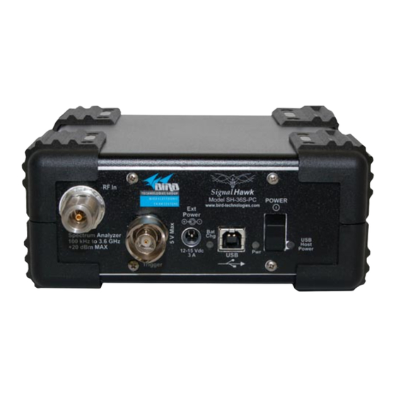
Introduction Looking at the SignalHawk Figure 3 PC SignalHawk Controls and Indicators Item Description Spectrum Analyzer Port, N(F) RF input, +20 dBm max. BNC(F) external trigger input, 5V TTL 2.1mm DC jack for external power supplies Battery Charge Indicator USB Type B for PC connection Charge Indicator Light Power Switch USB Host Power Indicator... - Page 20 Bird Technologies Figure 4 SignalHawk Rack-Mount Controls and Indicators Front Rear Item Description Power Button Power Indicator Pass-Thru LAN Connector Host Indicator CAUTION Do not block the fan’s airflow to prevent overheating. RS-232 Connector LAN Connector AC Power Connector AC Power Switch...
-
Page 21: Power Supply - Pc Signalhawk
Introduction Power Supply - PC SignalHawk Internal Battery The PC SignalHawk has an internal, rechargeable, lithium-ion battery pack that will operate the unit for a minimum of 3 hours of continuous use. Recharging time, from a full discharge, is approximately 4 hours. Note: When the unit is shipped from the factory, the battery may not be fully charged. -
Page 22: Power Supply - Rack-Mount Signalhawk
Bird Technologies Power Supply - Rack-Mount SignalHawk AC Power Connector The AC Power connector provides operating power for the Rack-Mount SignalHawk. The AC power supply cord is also the line disconnect device for this product. Use the supplied AC power cord or an approved... -
Page 23: Spectrum Analyzer Quick Start
Introduction Spectrum Analyzer Quick Start CAUTION Spectrum Analyzer has a +20 dBm (100 mW) max. RF input. Exceeding the maximum input will damage the SignalHawk. If unsure of power levels, measure the test connection with a power sensor before using the SignalHawk. 1. - Page 24 Bird Technologies 7. In the Start menu, select the desired measurement. "Spectrum Analysis Measurement" on page 52. "Occupied Bandwidth Measurement" on page 53. "Channel Power Measurement" on page 55. "Adjacent Channel Power Measurement" on page 57. "Time Domain (Zero Span)" on page 59 "Field Strength Measurement"...
-
Page 25: Chapter 2 Pc Signalhawk Set-Up
Chapter 2 PC SignalHawk Set-Up Installing the SignalHawk Program Note: Install the PC software before connecting the PC SignalHawk for the first time. 1. Insert installation CD. 2. Select Install Software when prompted. Note: Set-up will inspect the computer for any missing operating system prerequisites. - Page 26 Bird Technologies Figure 5 Found New Hardware Wizard 11. Click “Next”. 12. Follow the instructions that are presented. 13. Click “Finish” in the Completing the Found New Hardware Wizard window. Figure 6 Completing the Found New Hardware Wizard 14. Launch the SignalHawk program.
- Page 27 PC SignalHawk Set-Up Figure 7 Select DSP Device List...
- Page 28 Bird Technologies...
-
Page 29: Chapter 3 Rack Mount Signalhawk Set-Up
Chapter 3 Rack Mount SignalHawk Set-Up Installing the SignalHawk into a Rack CAUTION Do not block the fans airflow to prevent overheating. The Rack-Mount SignalHawk is a short-depth, 2 rack-unit (RU) device designed for installation into standard 19" equipment test racks. It can also be used free-standing. -
Page 30: Connecting The Rack-Mount Via Usb Connection
Bird Technologies Figure 8 Installing the SignalHawk into a Rack Rack Mount SignalHawk Mounting Screws and Washers Connecting the Rack-Mount via USB Connection 1. Insert installation CD into host PC. 2. Select Install Software when prompted. Note: Install the PC software before connecting the Rack Mount SignalHawk for the first time. - Page 31 Rack Mount SignalHawk Set-Up 9. Turn power on. 10. Select “Install the software automatically…” in the Found New Hardware Wizard window. Note: This procedure is performed when connecting either a PC or Rack-Mount SignalHawk for the first time. Driver installation is required for every distinct SH-36S-PC or SH- 36S-RM connected to the computer.
-
Page 32: Connecting Remotely Via Lan/Wan Connection
Bird Technologies Connecting Remotely via LAN/WAN Connection Note: The Rack-Mount SignalHawk provides the follow- ing connections to a network: • 10/100 auto sensing RJ45 Ethernet connector • Half and full duplex support • IP address: 192.168.1.10 • Subnet Mask: 255.255.255.0 Configuring a Basic Network Connection 1. - Page 33 Rack Mount SignalHawk Set-Up Click Finish. g. Click Close. 3. Configure TCP/IP settings on the client computer: Note: The client computer may have TCP/IP settings pre- viously configured. Changing settings may prevent access to other network resources such as the Internet or file sharing. Consult with your network administrator before making any changes.
- Page 34 Bird Technologies Note: Depending on which version of Windows is being used, the Windows Security or the Log On to Win- dows dialog box appears at this time. d. In the Windows Security or Log On to Windows dialog box, type user credentials.
- Page 35 Rack Mount SignalHawk Set-Up Figure 11 Rack-Mount SignalHawk Connection Diagram...
-
Page 36: Connecting A Remote Computer To The Host Computer
Bird Technologies Connecting a Remote Computer to the Host Computer To connect your home computer, which is the client (or remote) com- puter to the Rack Mount, follow these steps: 1. On your home computer, click Start, point to All Programs, and then point to Accessories. -
Page 37: Changing The Password On Auto Logon
Rack Mount SignalHawk Set-Up Changing the Password on Auto Logon 1. Go to the Start Menu. 2. Select All Programs 3. Select Bird Technologies Group. 4. Go to Utilities. 5. Go to Automatic Logon Utility. 6. Enter a username and new password. - Page 38 Bird Technologies...
-
Page 39: Chapter 4 Settings
Bird Technologies Group. Help Menu Key Displays the Help options but does not exit the current screen. Click on the... - Page 40 Bird Technologies Operations Manual (Quick Start Guide) - This manual contains quick start steps for measurements and for the Menu keys. Menu List - Displays the list of all measurements available in the active operating mode. This list can be expanded and collapsed to reveal or hide more detail about the measurement, such as setup parameters and custom configurations.
- Page 41 Settings Figure 13 SignalHawk Start Menu - Spectrum Analyzer Item Description Name of measurement being used Menu Selection labels Go to the Help menu. Select Esc/Back to return here. There are two functions in the help menu. Enter goes to a menu. Esc will exit a menu. Go to the Utilities menu.
-
Page 42: Setup Menu
Bird Technologies Setup Menu The Setup Menu allows access to saved setups and settings used previously on the SignalHawk. Click on Setup to access the menu. Figure 14 Setup Menu Quick Save Setup The saved settings are stored as a file in the internal drive of the host PC. -
Page 43: Label & Save Setup
Settings Label & Save Setup Figure 15 Setup Menu - Save Labels and saves the settings for a setup for future use. To save a Setup: 1. Click on Save Trace. 2. Enter a file name. Recall Setup Recalls a saved setup and sets the instrument parameters to run the recalled setup. -
Page 44: Delete
Bird Technologies Figure 16 Setup - Manage Setup Files Delete Deletes the selected Setup on the list. Delete All Setups Deletes all of the Setups on the list. View Setup See “View Setup” on page 28 in the Setup Menu. -
Page 45: Recall Setup
Settings Recall Setup Recalls a saved setup and sets the instruments parameters to run the recalled setup. Delete Deletes the displayed Setup. Top of List Displays the Setup from the top of list of saved Setups. Bottom of List Displays the Setup from the bottom of list of saved Setups. View Next Setup Displays the next Setup on the list of saved Setups. -
Page 46: Looking At The Screen
Bird Technologies Looking At The Screen Figure 18 General Screen Features Item Description Name of selected measurement Sweep display area Marker Date and time Name of setup file being used Menu selection labels Menu key labels Help tips for the current screen... -
Page 47: Freq & Span Menu
Settings Freq & Span Menu Figure 19 Freq & Span Menu In the Freq & Span Menu the range of frequencies to sweep are specified. The SignalHawk can sweep frequencies between 100 kHz and 3.6 GHz. Frequencies can be selected at spans from 1 kHz up to the entire range of the instrument. -
Page 48: Start / Stop Freq And Center / Span
Bird Technologies Start / Stop Freq and Center / Span These settings control the frequency range being swept. Note: “Center / Span” are used in this manual, but using “Start / Stop Freq” achieves the same results. After clicking the menu selection, it will highlight the active function. - Page 49 Settings Figure 20 Example, Freq List Recently Used Bands...
-
Page 50: Bw & Sweep Menu
Bird Technologies BW & Sweep Menu The bandwidth menu includes functions that control sweep speed and accuracy, and has the interface for customizing sweep triggers. When two signals are separated by a freq distance equal to the Resolu- tion BW, a 3 dB dip between them will appear on the screen. This is the minimum resolvable frequency spacing. -
Page 51: Resolution & Video Bw Modes
Settings Click on the Resolution BW selection then use the arrow keys or the mouse wheel to enter the desired bandwidth. RBW goes from 100 Hz - 1 MHz, steps of 1 / 3 / 10 (e.g.: 1 kHz to 3 kHz to 10 kHz to 30 kHz, etc.) Video BW Mode (VBW) determines how much smoothing takes place. -
Page 52: Resolution & Video Bw
Bird Technologies Resolution & Video BW Click on the selection to highlight it. Then: Up/Down Keys - Change the bandwidth incrementally. Left/Right Keys - Change the bandwidth from min to max. Mouse Scroll Wheel - Change the bandwidth incrementally. Span/RBW Click on the Span/RBW selection then enter the desired ratio. -
Page 53: Detection Mode
Settings Detection Mode Depending on measurement settings, many more data points are col- lected than there are pixels on the screen. Detection modes allow the user to choose how the collected data in each pixel is represented. + Peak Detection Returns the maximum value of the data collected for each display pixel. -
Page 54: Sweep
Bird Technologies Sweep Sweep sets up the properties of individual sweeps that the Signal- Hawk performs. It can set whether the sweeping is continuous or single, and the properties of video triggers (if enabled). Figure 25 Example, Sweep More Figure 26... -
Page 55: Single
Settings Single Performs a single sweep. Before a single sweep is triggered, the Sig- nalHawk will display the previous sweep. To begin a sweep, press the Manual Trigger soft key. After the sweep finishes, it will display the results and stop sweeping. Trigger - Sets the type of trigger that initiates a sweep. -
Page 56: Video
Bird Technologies Figure 27 Example, Low Level / High Level / Rise Edge / Fall Edge / Either Edge Video Note: This can only be used if the Time Domain measure- ment is enabled. See “Time Domain (Zero Span)” on page 59. -
Page 57: Ampt & Trace Menu
Settings Ampt & Trace Menu Figure 28 Example, Ampt & Trace Menu Autoscale Resizes the graph to fit the whole trace on the screen. This function will change the reference and scale of a trace. Reference Sets the y-axis value at the top of the graph. Scale Sets the dB value of each partition of the graph on a scale from 1 to 15. -
Page 58: Preamp
Bird Technologies Preamp Controls the built-in amplifier on the signal input. This lowers the noise floor, allowing very low power signals be detected, by giving a 24 dB nominal gain boost. Note: Attenuation is automatically disabled to 0 when Preamp is activated. -
Page 59: Min Hold
Settings Min Hold Holds and displays the lowest point of any given sweep until Min Hold is turned off. Average Displays the running average of multiple readings which is used to smooth a signal and decrease noise amplitude. Average Readings Sets the number of averaged readings. -
Page 60: Mark & Limit Menu
Bird Technologies Mark & Limit Menu Figure 30 Example, Mark & Limit Menu Select Marker Changes the active marker. There are six markers to choose from (measure- ments that use some of the markers for data display have less selectable markers). -
Page 61: Markers Detect
Settings Markers Detect Toggles the functionality of the submenu between finding peaks or finding valleys. Threshold The threshold offset, displayed on the first line, is used to calculate the threshold level, displayed on the second line, above the noise floor. Note: The low level peaks below the threshold level are fil- tered out. -
Page 62: Marker More
Bird Technologies Marker More Sets the properties of active markers through the following attributes: RSSI (Received Signal Strength Indicator) Turns the audio indicator On or Off (an electronic ping). See “Received Signal Strength Indicator (RSSI)” on page 61. Volume Sets the volume of the electronic ping generated from the RSSI. - Page 63 Settings Figure 32 Example, Mask List Once a mask is selected, it is controlled by the following options: Freq Lock - Locks the mask onto the selected band even if the frequency is changed. EM to Max Peak - Sets mask’s reference level to the maximum peak in each sweep.
-
Page 64: File & Help Menu
Bird Technologies File & Help Menu When File & Help is clicked, menu selections for saving the current trace, selecting the utility option, activating the logging feature, and accessing help features (Fig. 34) are enabled. A trace is saved as a file and stored in the default file location of the host PC. -
Page 65: Log Traces
Settings Figure 35 Example, Save Trace Log Traces Saves a sweep every 60 seconds and assigns a default name to each save. Recall Trace Opens up a submenu with three options: Recall Trace Displays a saved trace on the screen. Recall &... - Page 66 Bird Technologies...
-
Page 67: Chapter 5 Measurements
Chapter 5 Measurements Spectrum Analysis, measuring the power at each frequency in the sweep range, is the basic measurement. The other measurements interpret that data to provide useful results. In the Spectrum Analyzer mode, the following measurements can be used: "Spectrum Analysis Measurement"... -
Page 68: Spectrum Analysis Measurement
Bird Technologies Spectrum Analysis Measurement Spectrum Analysis measures the power at each frequency in the range shown on the screen. From the Spectrum Analyzer list on the Start Menu, select Spectrum Analysis then press the Enter key. Figure 36 Example, Spectrum Analysis, Frequency and Span Screen... -
Page 69: Occupied Bandwidth Measurement
Measurements Occupied Bandwidth Measurement Occupied Bandwidth measures the frequency band bandwidth that contains a specified percentage of the total power of the signal. It gives best results with single-peaked signals. Bandwidth can be defined in two ways. Both give measurement results in Hz units. Threshold Modes The calculated occupied bandwidth represents the user specified percent of the total power of the displayed span. - Page 70 Bird Technologies Figure 38 Example, Occupied Bandwidth - % STEP 1 STEP 2 Note: Limit can be set without changing the Threshold Mode. Figure 39 Example, Occupied Bandwidth - dBc STEP 1 STEP 2 Note: Limit can be set without changing the Threshold Mode.
-
Page 71: Channel Power Measurement
Measurements Channel Power Measurement Channel Power measures the Integration Bandwidth, the total power over a frequency range, concentrated on the center frequency of the sweep. It is useful for channelized (frequency-division multiplexed) signals. Results are shown in both total power in the channel (in dBm or Watts), and spectral density (dBm or Watts per Hz). - Page 72 Bird Technologies Figure 41 Example, Channel Power, Integration Bandwidth STEP 2 STEP 3...
-
Page 73: Adjacent Channel Power Measurement
Measurements Adjacent Channel Power Measurement Adjacent Channel Power measures the relative power of frequency bands adjacent to a central channel. This is often used to identify power leakage from the center channel into the adjacent channels. The total power in the central (main) channel is displayed in dBm (Ch Power), and the power in the adjacent channels is displayed as dB below and above the main channel power (Dn ACPR and Up ACPR). - Page 74 Bird Technologies Figure 42 Example, Adjacent Channel Power Adjacent Width Guardband Adjacent Guardband Channel Channel STEP STEP STEP Measurement Settings Figure 43 Example, Adjacent Channel Power, Bandwidth Settings STEP 4 STEP 5...
-
Page 75: Time Domain (Zero Span)
Measurements Time Domain (Zero Span) In Time Domain, the amplitude of a single frequency is measured, rather than sweeping a range of frequencies. The SignalHawk mea- sures and displays the amplitude of the frequency for a specified period (sweep time) and refreshes during the next sweep. The Time Domain trace resembles the horizontal line display on an oscilloscope. -
Page 76: Field Strength Measurement
Bird Technologies Field Strength Measurement Field Strength measures the signals reaching an antenna. The SignalHawk automatically corrects the sweep data for the antenna’s gain and frequency dependence and displays it in dBm / m. 1. Connect an antenna to the RF In connector on the SignalHawk. -
Page 77: Received Signal
Measurements Received Signal Strength Indicator (RSSI) RSSI provides an audible indication at the frequency of the current marker. It will beep faster as the received signal strength goes up and slows as it goes down. Similar to Water Fall, power is linearly mapped to a range of 0-210 using the same range as for the Water Fall for simplicity. -
Page 78: Demodulate Signal
Bird Technologies Demodulate Signal Removes the carrier and sends the signal to the internal speaker or headphones. The SignalHawk can demodulate AM, narrowband FM, and wideband FM signals. It can also set the specific frequency and volume. 1. Set the type of demodulation: a. -
Page 79: Carrier-To-Interference Ratio
Measurements Carrier-to-Interference Ratio Calculates the ratio of the carrier signal power to the power level of the noise and interference signals. To determine the ratio, two measurements need be done. First sweep should be the carrier and interferer. The second sweep should be the interferer alone. - Page 80 Bird Technologies Figure 49 Example, Carrier-to-Interference Ratio - Carrier Off STEP 4 Measurement Settings...
-
Page 81: Out-Of-Channel Spurious
Measurements Out-of-Band and In-Band, Out-of-Channel Spurious Note: These two measurement methods are not listed on the interface. Out-of-Band & In-Band, Out-of-Channel Spurious measures the distortion and interference inside or outside a system band. 1. Click on Mark & Limit. 2. Click on the Marker 1 2 3 4 5 6 selection to select marker 1. Note: The bracketed number indicates the active marker. - Page 82 Bird Technologies...
-
Page 83: Chapter 6 Utilities
Chapter 6 Utilities With SignalHawk’s built-in utilities, information about the instrument is displayed. The Menu keys provide information about the software, hardware, and data files. Utilities can be accessed by clicking on Utilities from the Start Menu screen, or by clicking on File & Help from a measurement screen then click on Utility. -
Page 84: Utility Main Menu
Bird Technologies Utility Main Menu Version Info Click on this to view general information such as how to contact Bird Technologies Group. The selections for this menu provide access to user help and the Win- dows operating system. Utility Main Menu Selections Spectrum Analyzer Help Click on this selection to display the SignalHawk Start-up Instructions. - Page 85 Utilities Figure 51 PC SignalHawk Directory 5. Copy the csv file of the list to be edited to the desktop of the PC. 6. Open the csv file. 7. Add custom information into the list. 8. Copy the csv file back into the My Lists directory. Note: The computer will ask for verification to overwrite the file in the directory.
- Page 86 Bird Technologies...
-
Page 87: Chapter 7 Pc Tool
Chapter 7 PC Tool Bird’s SignalHawk PCTool enables the use of a PC to store measure- ment data, transfer it between units, and do individual analysis. Traces can be transferred from the SignalHawk to the PC and back. One or more saved traces can be opened and compared. -
Page 88: Menu Bar
Bird Technologies Menu Bar File Presents commands to Open, Close, Save, Export, and Print Signal- Hawk files that are stored on the PC. Note: By default, traces will be saved to the “My Traces”, which is a subfolder under the folder where the PCTool was installed. -
Page 89: Tool Bar
PC Tool Tool Bar Use the tool icons to perform the tasks that are available on the Menu bar. Save Saves a copy of a graph. Open Opens a graph. Cuts a trace from a graph. Copy Copies a trace from a graph. Paste Pastes a trace onto a graph. -
Page 90: Zoom Out
Bird Technologies Zoom Out Decreases the focus from a specific area of a graph. Autoscale Graph Resizes the axis to fit all traces on the graph. Add Markers Drops a marker onto a graph. Add to Upper Limit Line Adds a limit line to the graph. -
Page 91: Vna Tool Bar
PC Tool VNA Tool Bar Note: There is an addendum, with additional options, to the menu bar when the PC Tool is reading a VNA file. Note: This section does not apply to PC and Rack Mount SignalHawks. Match Sets the current trace to a Match measurement display. Distance to Fault Sets the current trace to a Distance to Fault display. -
Page 92: Options Dialog Box (View>Options)
Bird Technologies Options Dialog Box (View>Options) The Options dialog box contains six tabs - Scale, Units, Markers, Limits1, Limits 2, and Labels. Select a tab and enter or edit specific values for the currently active graph. Scale Tab 1. Enter the x- and y- axis. -
Page 93: Markers Tab
PC Tool Markers Tab When a frequency or distance for a marker is entered, the marker will be set to the datapoint closest to that frequency or distance. The actual frequency of the marker will replace the value entered and will also display on the screen below the graph area. -
Page 94: Limits 2 Tab
Bird Technologies Figure 57 Example, Limits 1 Tab Limits 2 Tab Note: The options displayed on this tab will change slightly depending on the type of graph opened. Note: The upper limit fails any datapoints that are above the line. -
Page 95: Labels Tab
PC Tool Labels Tab Creates a title, subtitle, and a trace name for the displayed trace. The title will be in larger letters and centered above the graph. The sub- title will be smaller. Edit a trace name by typing in the list of traces on this tab. The trace and date will be located above the graph and on the left. - Page 96 Bird Technologies...
-
Page 97: Chapter 8 Maintenance
Harsh or abrasive detergents, and some solvents, can damage the unit and labels. Clean the Bird SignalHawk only with a soft cloth dampened with mild detergent and water. Do not use any other type of cleaning solution. Charging the Battery The internal battery pack will automatically recharge when the SignalHawk is powered from the AC or cigarette lighter adapter. -
Page 98: Updating The Firmware
Updating the Firmware Note: There are two different firmware files: one contain- ing the DSP image and the other containing the FPGA image. 1. Navigate to Bird Technologies Group>PC SignalHawk in the Start menu. 2. Click on Firmware Update Wizard. - Page 99 Maintenance 4. Connect the unit to the PC via USB cable. 5. Turn on the SignalHawk. 6. Select “Install the software automatically...” if the “Found New Hardware Wizard” is presented. Note: Both program wizards will run co-currently. See “Installing the SignalHawk Program” on page 9 for the PC SignalHawk.
-
Page 100: Updating The Firmware On A
Bird Technologies Updating the Firmware on a Remote Rack Mount SignalHawk 1. Go to http://birdtechnologies.thomasnet.com/item/all-categories-test- equipment/-categories-test-equipment-sh-36-signalhawk-series/sh- 36s-rm. 2. Download the Rack Mount SignalHawk software upgrade to a local PC. 3. Connect the remote computer to the host computer. See “Connect- ing a Remote Computer to the Host Computer”... -
Page 101: Troubleshooting
Maintenance 8. Log into the remote computer. 9. Stop the Rack Hawk application. 10. Copy the PC Hawk software upgrade from the local PC to the Rack Hawk at XXXXXXXXXXXX. 11. Double click “Setup” and follow the upgrade instructions. Troubleshooting Any service procedure not covered in this manual should be referred to an authorized service facility. -
Page 102: Customer Service
If you need to return the unit for any reason, request an RMA through the Bird Technologies website (link shown below). All instruments returned must be shipped prepaid and to the attention of the RMA number. -
Page 103: Specifications
Maintenance Specifications Model Number Model Name SH-36S-RM Rack-Mount SignalHawk SH-36S-PC PC SignalHawk SH-36S-RM Frequency 100 kHz to 3.6 GHz Range 1 Hz Resolution σ ± 1 ppm (2 ) of measured frequency Uncertainty σ ± 1 ppm / year (2 Aging σ... - Page 104 Bird Technologies Amplitude σ ± 1.5 dB max (2 ), ±1.0 dB typical, Accuracy >-50 dB ref, 15 to 35 °C, max detector Running display average, 2 to 100 sweeps Averaging sample, +peak, –peak, average, video Detection Modes average Measurements Analyzes radio frequency spectrum.
- Page 105 Maintenance Measurements 6 Markers; Modes: On/Off, Standard, Marker Markers to Max Peak, Marker to Next Peak, Marker Freq to Center, Marker Ampt to Ref Level, Marker Delta, Marker Type Line/Icon, Marker Noise, All Marker to Peaks, All Markers Off. Also, Marker to Max/Min Peak Reference the user manual and design User Interface specification for further details.
- Page 106 Bird Technologies General Specifications Dual fuse line/neutral or single line fuse/ AC Fuse Options neutral shorting bar (neutral un-fused) Chassis Grounding Terminal #10-32 x ¾” UNC Forced air, front panel intake Cooling Method 0 to 50 °C (MIL-PRF-28800F, Class 3) Operating Temperature –20 to +80 °C...
-
Page 107: Distortion & Danl
Maintenance PC Software Local USB client, single client only (local or Client Priority remote) Input Precision N-F Connector 50 ohms, nominal RF Input Impedance 1.8:1 typ, 2.0:1 max RF Input VSWR (internal attenuator = 10dB or greater) ± 50 V Max DC Input +20 dBm;... - Page 108 Bird Technologies Amplitude -150 dBm to +30 dBm Display Range 66 dB; Third-order IM products, Intermodulation-Free Two -20 dBm inputs, Reference = -10 dBm Dynamic Range -135 dBm; 24 dB gain, 100 Hz RBW, Displayed Average 10 Hz VBW, average detection Noise Level (DANL) –80 dBm;...
- Page 109 Maintenance Measurements Sample, +peak, –peak, average, video average Detection Modes Single, free run Trigger Modes Internal, external TTL, internal video Trigger Sources Rising edge, falling edge, any edge, trigger on HIGH, External Trigger Types trigger on LOW TTL Levels External Trigger Level User-settable, 100 µs to 1000 ms after trigger received External Trigger Delay before starting sweep...
- Page 110 Bird Technologies General Specifications 4600m above sea level (MIL-PRF-28800F, Class 2) Altitude, Max 3 lbs Weight 6.5” x 6.5” x 2.5” thk, not including connectors Dimensions, Max 61326:1997 +A1:1998 and A2:2001 – EMC CE Compliance 61010-1:2001 – Safety 89/336/EEC - EMC...
-
Page 111: Parts List
Maintenance Parts List Note: Contact Bird Service Center for parts information. Standard Accessories Description Part No. Operations Manual - PDF electronic copy 920-SHPC-OPS 1 Start-Up Instructions 920-SHPC-REF AC Line Cord 4421-055 USB Cable, 10 ft, USB 2.0 certified, USB A male to USB... -
Page 112: Optional Accessories
Bird Technologies Optional Accessories SH-36S-PC General Description Part No. User Manual, paper copy 920-SHPC-OPS Field Strength Antenna, 136 to 221 MHz, ANT-100 Field Tunable, 0 dB Gain Field Strength Antenna, 400 to 512 MHz, ANT-400 Field Tunable, 0 dB Gain... -
Page 113: Sh-36S-Rm
Maintenance SH-36S-RM General Description Part No. User Manual, paper copy 920-SHPC-OPS USB Cable, 10 ft, USB 2.0 certified, 5A2653-10 USB A male to USB B male Attenuator, 100 W, 40 dB, NM/NF, 2.4 GHz 100-SA-MFN-40 Attenuator, 50 W, 30 dB, NM/NF.4 GHz 50-A-MFN-30 Attenuator, 25 W, 30 dB, NM/NF, 4 GHz 25-A-MFN-30... -
Page 114: Rohs
Bird Technologies ROHS Part Toxic or hazardous Substances and Elements Name Lead Mercury Cadmium Hexavalent Polybro- Polybro- (Pb) (Hg) (Cd) Chromium minated minated (Cr(VI)) biphenyls diphenyl (PBB) ethers (PBDE) Copper Alloy Florescent Backlight Printed Circuit Assembly O: Indicates that this toxic or hazardous substance contained in all of the homogeneous materials for this part is below the limit requirement in SJ/T11363-2006. -
Page 115: Appendix 1
Appendix 1 Menu Maps Spectrum Analyzer Menu Maps The illustrations in this section show the options that are available when selecting a measurement function. Figure 67 Menu Map, Freq & Span Menu, All Measurements Note: If a channelized band is selected, there will be an extra selection named Channel (see Fig. - Page 116 Bird Technologies Figure 68 Menu Map, Freq/Span Menu, Channelized Band Note: If a channelized band is selected, the system displays the Channel selection in addition to those shown in Fig. 67.
- Page 117 Maintenance Figure 69 Menu Map, BW & Sweep Menu, All Measurements BW & Sweep Resolution BW Mode Auto /Man Sweep: Sweep: Positive Peak Cont / Single Cont / Single Resolution 3 kHz Negative Trigger Trigger Peak Free Rep Free Single Video BW Mode Auto /Man...
- Page 118 Bird Technologies Figure 70 Menu Map, Amplitude, All Measurements...
- Page 119 Maintenance Figure 71 Menu Map, Measurement, All Measurements...
- Page 120 Bird Technologies Figure 72 Menu Map, Mark & Limit Menu, All Measurements...
- Page 121 Maintenance Figure 73 Menu Map, File & Help, All Measurements...
-
Page 122: Setup Function Menu Maps
Bird Technologies Setup Function Menu Maps Figure 74 Map, Setup (Mode), Main Screen... -
Page 123: Appendix 2 Software License Terms
MICROSOFT® WINDOWS® XP PROFESSIONAL FOR EMBEDDED SYSTEMS (1-2 CPU VERSION) These license terms are an agreement between you and Bird Technol- ogies Group. Please read them. They apply to the software included on this device. The software also includes any separate media on which you received the software. - Page 124 TCP/IP. 3. SCOPE OF LICENSE. The software is licensed, not sold. This agreement only gives you some rights to use the software. Bird Technologies Group and Microsoft reserve all other rights. Unless applicable law gives you more rights despite this limitation, you may use the software only as expressly permitted in this agree- ment.
- Page 125 Maintenance Technologies Group. Except and only to the extent permitted by applicable law despite these limitations, you may not: work around any technical limitations in the software; reverse engineer, decompiler or disassemble the software; make more copies of the software than specified in this agreement; publish the software for others to copy;...
- Page 126 Bird Technologies Web Content Features. Features in the software can retrieve related content from Microsoft and provide it to you. To provide the content, these features send to Microsoft the type of operating system, name and ver- sion of the software you are using, type of browser and language code of the device where the software was installed.
- Page 127 Authenticity label with a genuine copy of the software identifies licensed software. To be valid, this label must be affixed to the device, or included on or in Bird Technologies Group’s software packaging. If you receive the label separately, it is not valid. You should keep the label on the device or packaging to prove that you are licensed to use the software.
- Page 128 Micro- soft or its affiliates. When allowed by your local laws, Bird Technologies Group and Microsoft exclude implied war- ranties of merchantability, fitness for a particular purpose and non-infringement.
-
Page 129: Limited Warranty
Limited Warranty All products manufactured by Seller are warranted to be free from defects in material and workmanship for a period of one year, unless otherwise specified, from date of shipment and to conform to applica- ble specifications, drawings, blueprints and/or samples. Seller’s sole obligation under these warranties shall be to issue credit, repair or replace any item or part thereof which is proved to be other than as warranted;... - Page 130 Bird Technologies...
Need help?
Do you have a question about the SignalHawk SH-36S-RM and is the answer not in the manual?
Questions and answers