
Related Manuals for BIRD Thruline 4304A


Summary of Contents for BIRD Thruline 4304A
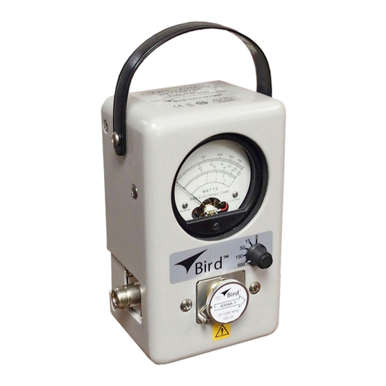
- Page 1 RF Directional Thruline® Wattmeter MODEL 4304A Operation Manual ©Copyright 2016 by Bird Technologies, Inc. Instruction Book Part Number 920-4304A Rev. F Thruline® and Termaline® are registered trademarks of Bird Electronic Corporation...
-
Page 2: Safety Precautions
Safety Precautions The following are general safety precautions that are not necessarily related to any specific part or procedure, and do not necessarily appear elsewhere in this publication. These precautions must be thoroughly understood and apply to all phases of operation and maintenance. WARNING Keep Away From Live Circuits Operating Personnel must at all times observe general safety precautions. -
Page 3: Safety Symbols
Safety Precautions Safety Symbols WARNING Warning notes call attention to a procedure, which if not correctly performed, could result in personal injury. CAUTION Caution notes call attention to a procedure, which if not correctly performed, could result in damage to the instrument. The caution symbol appears on the equipment indicating there is important information in the instruction manual regarding that particular area... -
Page 4: Safety Statements
RF Directional Thruline® Wattmeter 4304A CAUTION Above 800 MHz, do not exceed 150 W RF power. CAUTION RF power must not exceed range switch setting. CAUTION Do not attempt to remove the RF center conductor. This will damage the line section. - Page 5 Safety Precautions ENDOMMAGER LE DISPOSITIF DE PROTECTION DE L’INSTRUMENT. IMPIEGO QUALORA QUESTO STRUMENTO VENISSE UTILIZZATO IN MODO DIVERSO DA COME SPECIFICATO DAL PRODUTTORE LA PROZIONE DI SICUREZZA POTREBBE VENIRNE COMPROMESSA.
- Page 6 RF Directional Thruline® Wattmeter 4304A SERVICE SERVICING INSTRUCTIONS ARE FOR USE BY SERVICE - TRAINED PERSONNEL ONLY. TO AVOID DANGEROUS ELECTRIC SHOCK, DO NOT PERFORM ANY SERVICING UNLESS QUALIFIED TO DO SO. SERVICIO LAS INSTRUCCIONES DE SERVICIO SON PARA USO EXCLUSIVO DEL PERSONAL DE SERVICIO CAPACITADO.
- Page 7 Safety Precautions RF VOLTAGE MAY BE PRESENT IN RF ELEMENT SOCKET - KEEP ELEMENT IN SOCKET DURING OPERATION. DE LA TENSION H.F. PEAT ÊTRE PRÉSENTE DANS LA PRISE DE L'ÉLÉMENT H.F. - CONSERVER L'ÉLÉMENT DANS LA PRISE LORS DE L'EMPLOI. HF-SPANNUNG KANN IN DER HF-ELEMENT-BUCHSE ANSTEHEN - ELEMENT WÄHREND DES BETRIEBS EINGESTÖPSELT LASSEN.
-
Page 8: About This Manual
RF Directional Thruline® Wattmeter 4304A About This Manual This manual covers the operating and maintenance instructions for the following models: 4301 4305A 4431 4527 4521 4522 4526 Changes to this Manual We have made every effort to ensure this manual is accurate. If you discover any errors, or if you have suggestions for improving this manual, please send your comments to our Solon, Ohio factory. -
Page 9: Table Of Contents
Table of Contents Safety Precautions ......... i Safety Symbols . - Page 10 Setup Test ..........19 Calibrating a Bird Element 4304A-1 ......19 Storage .
-
Page 11: Chapter 1 Introduction
Introduction Purpose and Function The Bird 4304A Wattmeter is an in-line sensor that measures RF power and load match in 50 coaxial transmission lines. It can be used with CW, AM, FM, and TV modulation, but not pulse modulation. It is supplied with a special broadband element with a frequency range of 25 to 1000 MHz. -
Page 12: Chapter 2 Theory Of Operation
Note: Z is the characteristic impedance of a uniform line section. For useful lines it is usually a pure resistance of 50. The RF circuit of the Bird 43 is a length of uniform air line with Z = 50. -
Page 13: Coupling Circuit
Thruline Wattmeter measurements are also independent of position along the transmission line. Like similar diode devices, the Bird 4304A indicates the carrier component of amplitude modulation, with very little response to side band components... -
Page 14: Load Power
WattsIntoLoad – Good load resistors, such as Bird Termaline loads, will give negligible reflected power. Standing Wave vs. Traveling Wave Viewpoint As mentioned previously, the Thruline Wattmeter reacts to forward and reverse traveling waves to measure power in a transmission line. - Page 15 Theory of Operation A trial is suggested – forget about VSWR for a few days and think in terms of = . The two meter readings, W and W , give a useful, approximate picture of the results without bothering to calculate the power ratio exactly. Consider that, for an antenna matching problem, the main objective usually is to minimize W .
- Page 16 RF Directional Thruline® Wattmeter 4304A Figure 4 Percent Reflected Power vs. VSWR (1.0 – 8.0)
-
Page 17: Component Testing
Theory of Operation Component Testing The Bird 4304A is very helpful in component testing, and may be employed in several ways: Note: Measuring small attenuations requires correction for nor- mal instrument errors. For two wattmeters, do this by simply con- necting the wattmeters directly, with no line between them, and adjusting their zero settings. -
Page 18: Impedance Mismatch
RF Directional Thruline® Wattmeter 4304A Impedance Mismatch In some cases it may be necessary to use the Bird 4304A with a non-50 transmission line. If the reflected power is less than 10% and the frequency is below 200 MHz, the resulting mismatch will not be too serious. At higher frequencies or reflected power levels, the load impedance will change when the wattmeter is removed. -
Page 19: Chapter 3 Installation
VSWR. Load Matching When a Bird 4304A is used to tune a load to a transmitter and a good match is obtained, removing the wattmeter will not change the match quality. A 50 load can terminate a 50 transmission line of any length without altering conditions at the transmitter. - Page 20 Transmission line theory shows that if the line length changes by exactly wavelength, the impedance at the transmitter will not change. So, to have identical match with the Bird 4304A in or out of the circuit, it is necessary to ...
- Page 21 Installation Figure 5 Cable Length / Wavelength Matching...
-
Page 22: Chapter 4 Operating Instructions
Chapter 4 Operating Instructions WARNING When working with RF powers of 200 watts or more, the potential of the center conductor of the line section will exceed 100 volts. Do not touch the center conductor while RF power is on. CAUTION Above 800 MHz, do not exceed 150 W RF power. - Page 23 Operating Instructions Figure 6 VSWR Conversion Graph (Reflected Power 0.2 – 20.0)
- Page 24 RF Directional Thruline® Wattmeter 4304A Figure 7 VSWR Conversion Graph (Reflected Power 0.01 – 1.00)
-
Page 25: Chapter 5 Maintenance
CAUTION Do not drop. Calibration could be disturbed or the meter could be damaged as a result. The rugged and simple design of the Bird 4304A means that it requires minimal routine maintenance. Cleaning It is important to keep the following surfaces clean: ... - Page 26 RF Directional Thruline® Wattmeter 4304A This manual does not list all malfunctions that may occur, or all corrective actions. If a malfunction is not listed or not corrected by the listed actions, contact the nearest Bird Service Center for assistance. Problem Possible Cause...
-
Page 27: Zero Adjust
RF power is being applied. Leaking RF energy is a potential health hazard. The Bird 4304A has Bird “QC” connectors which are designed to be easily changed. To change the connector, remove the four screws at its corners and then pull it straight out. -
Page 28: Line Section Replacement
7. Replace the line section and reassemble by reversing these steps. Note: The circuit board cannot be replaced in the field. If the cir- cuit board is defective, return the unit to a Bird Service Center. Meter Replacement ... -
Page 29: Calibration Checks
Maintenance Calibration Checks Setup Test Note: This test determines if the wattmeter needs recalibration: 1. The following equipment is required, connected in series with the Bird 4304A (Refer to Figure 9 RF source Low pass filter Reference, known accurate, wattmeter ... - Page 30 RF Directional Thruline® Wattmeter 4304A 2. Connect the calibration equipment as shown in Figure 10 3. Set the range switch to 15 and adjust the RF source to apply 12.5 watts at 100 MHz. 4. Adjust R9 ( ) until the 4304A meter indicates 12.5. Figure 11 5.
-
Page 31: Storage
Range Adjustment Potentiometers Storage When storing the Bird 4304A, turn the element so that the arrow points down and set the range switch to 5 W. This will shunt the meter circuit and protect the meter by dampening needle action. -
Page 32: Specifications
± 6% of full scale 512 – 1000 MHz ± 7% of full scale Impedance, Nominal Connectors Bird “QC”, Female, N or UHF, normally supplied Operating Position Dimensions (Nominal) 3-5/8”L x 4”W x 6-7/8”H (92 x 102 x 175 mm) Approximate Weight 4 lb. -
Page 33: Available "Qc" Type Connectors
Maintenance Available “QC” Type Connectors Connector Part Number Connector Part Number BNC-Female 4240-125 LT-Female 4240-018 BNC-Male 4240-132 LT-Male 4240-012 C-Female 4240-100 N-Female 4240-062 C-Male 4240-110 N-Male 4240-063 HN-Female 4240-268 SMA-Female 4240-336 HN-Male 4240-278 SMA-Male 4240-334 LC-Female 4240-031 7/16 Jack, IEC 4240-344 Type 169-4 LC-Male... -
Page 34: Limited Warranty
Limited Warranty All products manufactured by Seller are warranted to be free from defects in material and workmanship for a period of one (1) year, unless otherwise specified, from date of shipment and to conform to applicable specifications, drawings, blueprints and/or samples. Seller’s sole obligation under these warranties shall be to issue credit, repair or replace any item or part thereof which is proved to be other than as warranted;...
Need help?
Do you have a question about the Thruline 4304A and is the answer not in the manual?
Questions and answers