Table of Contents
Advertisement
Quick Links
Advertisement
Table of Contents

Related Manuals for BIRD 43


Summary of Contents for BIRD 43
- Page 1 INSTRUCTION BOOK RF DIRECTIONAL THRULINE® WATTMETER MODEL 43 Also Covers Models 4431, 43P And Series 4300, 4520 ©Copyright 2008 by Bird Electronic Corporation Instruction Book Part Number 920-43 Rev. H Thruline® and Termaline® are registered trademarks of Bird Electronic Corporation...
-
Page 2: Safety Precautions
Safety Precautions The following are general safety precautions that are not necessarily related to any specific part or procedure, and do not necessarily appear elsewhere in this publication. These precautions must be thoroughly understood and applied to all phases of operation and maintenance. Keep Away From Live Circuits Operating personnel must at all times observe general safety precautions. - Page 3 Bird Model 43 Wattmeter Safety Symbols WARNING Warning notes call attention to a procedure, which if not correctly performed, could result in personal injury. CAUTION Caution notes call attention to a procedure, which if not correctly performed, could result in damage to the instrument.
- Page 4 Caution Statements The following equipment cautions appear in the text whenever the equipment is in danger of damage, and are repeated here for emphasis. CAUTION For low reflection measurements, do not rotate the reflected power element to read forward power. Damage to the element or wattmeter could result.
- Page 5 Bird Model 43 Wattmeter BENUTZUNG WIRD DAS GERÄT AUF ANDERE WEISE VERWENDET ALS VOM HERSTELLER BESCHRIEBEN, KANN DIE GERÄTESICHERHEIT BEEINTRÄCHTIGT WERDEN. UTILISATION TOUTE UTILISATION DE CET INSTRUMENT QUI N’EST PAS EXPLICITEMENT PRÉVUE PAR LE FABRICANT PEUT ENDOMMAGER LE DISPOSITIF DE PROTECTION DE L’INSTRUMENT.
- Page 6 ANWEISUNGEN FÜR DIE WARTUNG DES GERÄTES GELTEN NUR FÜR GESCHULTES FACHPERSONAL. ZUR VERMEIDUNG GEFÄHRLICHE, ELEKTRISCHE SCHOCKS, SIND WARTUNGSARBEITEN AUSSCHLIEßLICH VON QUALIFIZIERTEM SERVICEPERSONAL DURCHZUFÜHREN. ENTRENTIEN L’EMPLOI DES INSTRUCTIONS D’ENTRETIEN DOIT ÊTRE RÉSERVÉ AU PERSONNEL FORMÉ AUX OPÉRATIONS D’ENTRETIEN. POUR PRÉVENIR UN CHOC ÉLECTRIQUE DANGEREUX, NE PAS EFFECTUER D’ENTRETIEN SI L’ON N’A PAS ÉTÉ...
-
Page 7: About This Manual
Chapter 7 - Specifications. An experienced operator can refer to Chapter 4 - Operating Instructions. All instructions necessary to operate the equipment appears in this chapter. If you are not using the Model 43, refer to Chapter 6 - Model Differences for instructions specific to your unit. Maintenance All personnel should be familiar with the preventive maintenance found in Chapter 5 - Maintenance. - Page 8 Changes to This Manual We have made every effort to ensure this manual is accurate. If you should discover any errors or if you have suggestions for improving this manual, please send your comment to our factory. This manual may be periodically updated. When inquiring about updates to this manual refer to the part number and revision level on the title page.
-
Page 9: Table Of Contents
Table of Contents Safety Precautions ......... i About This Manual . - Page 10 Installation ........
-
Page 11: Introduction
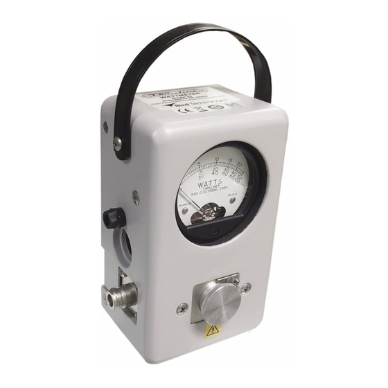
Electronic Corporation Catalog for details). Performance Characteristics and Capabilities The Bird 43 is portable, with an attached carrying strap. It has an aluminum housing and an easily removed back cover, with bumpers on the base and back that allow the meter to stand or lie flat. For additional protection, the microammeter is specially shock mounted. - Page 12 At each end of the line section are Bird Quick-Change RF connectors that may be interchanged with any other Bird “QC” connector. The wattmeter housing does not interfere with connector changes.
- Page 13 Figure 2 Bird 43 Thruline Wattmeter Outline Drawing...
- Page 14 Bird Model 43 Wattmeter...
-
Page 15: Theory Of Operation
For useful lines it is usually a pure resistance of 50 ohms. The RF circuit of the Bird 43 is a length of uniform air line with Z = 50 ohms. -
Page 16: Coupling Circuit
Bird Model 43 Wattmeter Coupling Circuit The coupling circuit that samples the travelling waves is in the Bird Plug-In Element. The element circuitry and its relationship to the rest of the Bird 43 are illustrated in Figure 3. Figure 3... -
Page 17: Load Power
Thruline Wattmeter measurements are also independent of position along the transmission line. Like similar diode devices, the Bird 43 indicates the carrier component of amplitude modulation, with very little response to side band components added by modulation. -
Page 18: Standing Wave Vs. Travelling Wave Viewpoint
Bird Model 43 Wattmeter Standing Wave vs. Travelling Wave Viewpoint As mentioned previously, the Thruline Wattmeter reacts to forward and reverse travelling waves to measure power in a transmission line. The standing wave viewpoint, also widely used, is highly developed both in theory and in practice. - Page 19 = 10 log VSWR scales and their attendant controls for setting the reference point have been intentionally omitted from the Bird 43. Experience using the Thruline Wattmeter for transmitter tune-up, antenna matching, etc. will show that the power ratio measurement is as useful in practice as the standing wave ratio.
- Page 20 Bird Model 43 Wattmeter Figure 4 Percent Reflected Power vs. VSWR (1.0 – 1.3)
- Page 21 Theory of Operation Figure 5 Percent Reflected Power vs. VSWR (1.0 – 8.0)
-
Page 22: Low Reflection Measurements
This method should not be used with element ranges differing by more than 10:1. For example, consider an 80 watt transmitter and a Bird 43 with 100 and 10 watt elements. Measure W with the 100 W element. -
Page 23: Transmitter Monitoring
The Thruline Wattmeter can be used for the continuous monitoring of transmitter output or reflected power, for instance in checking intermittent antenna or line faults. Component Testing The Bird 43 is very helpful in component testing, and may be employed in several ways: φ 1. VSWR or may be measured by placing the component under test between the wattmeter and a good load resistor. -
Page 24: Frequency Response
Frequency Response Bird Plug-In Elements have a flat frequency response over their specified operating range. A sample set of curves is shown in Figure 6. Notice that for the low power element, the rolloff outside its frequency band is more pronounced than for the high power elements. - Page 25 Theory of Operation Figure 6 Representative Frequency Response These curves are typical for all element types (H, A, B, C, D, ...) at their respective frequencies. Since a C type element has a frequency range of 100 - 250 MHz, response curves for other element types can be approximated by replacing the 100 and 250 MHz points on the chart with the extremes of the element’s frequency range, and recalc- ulating the other frequency points accordingly.
-
Page 26: Impedance Mismatch
Always divide the larger impedance by the smaller, since VSWR must always be greater than 1. As an example, consider using a Bird 43 to tune a 70 ohm line. If the load impedance is also 70 ohms, the wattmeter will measure a VSWR of 70/50 = 1.4. -
Page 27: Installation
Chapter 3 Installation When transporting the Bird 43, insert the original dust plug, or an element with the arrow pointing upward, in the element socket and secure with the catch. This will shunt the meter circuit and protect the meter by dampening needle action during handling and shipping. -
Page 28: Remote Installation
Bird Model 43 Wattmeter The Bird 43 is normally supplied with Quick-Change Female N type connectors. Other Bird “QC” connectors are available, refer to the Replacement Parts List in the Maintenance Chapter. Quick-Change connectors can be replaced by removing the 8-32 screw at each corner of the connector and then pulling it straight outward. - Page 29 Installation The RF line section of the Bird 43 lends itself very readily to panel mounting. A layout for the panel cut is given in Figure 7. The ⁄ thickness of the panel should be about inch. On thinner panels, build up the thickness with pads or washers to achieve a flush-face mounting.
- Page 30 Bird Model 43 Wattmeter...
-
Page 31: Operating Instructions
100 volts. Do not touch the center conductor while RF power is on. The Bird 43 uses plug-in elements to make measurements. The element’s frequency range and maximum power are listed on its label. - Page 32 Bird Model 43 Wattmeter Turn on the RF source. Read the power using the scale whose full-scale marking matches the element’s maximum power. Figure 8 Element Direction When readings are being made with the wattmeter connected to an auxiliary RF line section, do not put an element in the unused line section.
- Page 33 Operating Instructions Figure 9 VSWR Conversion Graph (Reflected Power 0.2 – 20.0)
- Page 34 Bird Model 43 Wattmeter Figure 10 VSWR Conversion Graph (Reflected Power 0.01 – 1.00)
-
Page 35: Load Matching
Operating Instructions Load Matching When a Bird 43 is used to tune a load to a transmitter and a good match is obtained, removing the unit will not change the match quality. A good 50 ohm load can terminate a 50 ohm transmission line of any length without altering conditions at the transmitter. - Page 36 Bird Model 43 Wattmeter Figure 11 Cable Length / Wavelength Matching...
-
Page 37: Maintenance
Chapter 5 Maintenance The rugged and simple design of the Bird 43 means that it requires minimal routine maintenance. Troubleshooting The following table contains troubleshooting information for problems that can occur during normal operation. Find the problem on the table, review possible causes, and perform the corrective action listed. -
Page 38: Cleaning
Bird Model 43 Wattmeter Intermittent or Dirty dc contact on element Clean contact (page 28) inconsistent Faulty transmission line or Inspect line meter reading antenna Sticky or defective meter Return wattmeter for service High VSWR or Foreign material in line... -
Page 39: Contact Adjustment
Maintenance If the RF line section seems dirty, do not loosen any connections. Clean accessible components as described above and use dry, clean air to blow out the interior. The outside of the meter housing can be cleaned with a soft cloth dampened with a mild detergent solution. -
Page 40: Zero Adjust
Bird Model 43 Wattmeter Zero Adjust The meter’s zero setting should be checked when no RF power is present. When no power is applied the pointer should rest exactly on zero. If adjustment is required, turn the adjustment screw until the pointer is set at zero (see Figure 12). -
Page 41: Customer Service
Maintenance Customer Service If you need to return the unit for any reason, contact the Bird Service Center for a return authorization. All instruments returned must be shipped prepaid and to the attention of Bird Service Center: Bird Service Center... -
Page 42: Bird 43 Replacement Parts List
Bird Model 43 Wattmeter Bird 43 Replacement Parts List Description Qty. Part Number Housing Assembly 4210-018 Cover Assembly 4210-005-1 Line Section Assembly 4230-018 Carrying Strap 8580A003 Dust Plug, Aluminum 3610-031 DC Connector Assembly 4230-010 DC Connector 7500-076 Microammeter 2080-002 Coaxial Cable Assembly... -
Page 43: Available "Qc" Type Connectors
Maintenance Available “QC” Type Connectors Connector Part Number Connector Part Number BNC-Female 4240-125 Open Term. 4240-363 # 10-32 Nut BNC-Male 4240-132 SC-Female 4240-090 C-Female 4240-100 SMA-Female 4240-336 C-Male 4240-110 SMA-Male 4240-334 HN-Female 4240-268 TNC-Female 4240-156 HN-Male 4240-278 TNC-Male 4240-160 LC-Female 4240-031 UHF-Female 4240-050... - Page 44 Bird Model 43 Wattmeter...
-
Page 45: Model Differences
Model Differences Bird 43P Peak Wattmeter The Bird 43P Thruline Wattmeter is the same as the Bird 43, with the added capability of measuring peak power in AM, SSB, and some pulse applications. A conversion kit (P/N 4300-400) is available to give peak reading capability to any standard Bird 43. -
Page 46: Rectangular Pulses
2. Grasp the back cover by the side tabs behind the line connectors and pull straight back to remove it. 3. Insert the Bird 43P between a reliable CW signal source and a 50 ohm load. 4. Insert an element with the appropriate power and frequency range into the Bird 43P. -
Page 47: Maintenance
Model Differences Maintenance Maintenance of the Bird 43P is the same as for the Bird 43 except for battery replacement. Battery life should typically be 48 hours. If the unit does not function properly in peak mode or if calibration cannot be achieved, the batteries may be low. -
Page 48: Bird 4301 Thruline Wattmeter
Bird Model 43 Wattmeter Bird 4301 Thruline Wattmeter The Bird 4301 Thruline Wattmeter is the same as the Bird 43 except for the following physical differences: The auxiliary DC connector on the Model 4301 can be used to connect to an accessory line section. Make the connection with a standard RG-... -
Page 49: Bird 4305A Thruline Wattmeter
Model Differences Bird 4305A Thruline Wattmeter The Bird 4305A Thruline Wattmeter is the same as the Bird 43 except for the following physical differences: The Bird 4305A’s dimensions are 4-5/16”L x 4”W x 6-7/8”H (110 x 102 x 175 mm), including element and bumper feet. The weight is 3.25 lb. -
Page 50: Bird 4431 Thruline Wattmeter
Bird Model 43 Wattmeter Bird 4431 Thruline Wattmeter The Bird 4431 RF Sampling Wattmeter is the same as the Bird 43 Thruline Wattmeter except for an RF signal sampler probe. The RF sampler provides a low power sample of the signal being transmitted through the wattmeter’s linesection. -
Page 51: Maintenance
Maintenance Do not make repairs to the probe assembly. If the sampler malfunc- tions, we recommend returning the unit to the Bird Service Center for repair. To replace the probe assembly, follow these instructions: 1. To reach the probe, unscrew the four 8-32 flat head screws securing the back cover. -
Page 52: Bird 4431 Replacement Parts List
Bird Model 43 Wattmeter Bird 4431 Replacement Parts List Only parts which are not used on the Bird 43 are listed here. Description Qty. Part Number Modified Housing (instead of 4210-018) 4431-011 Guide Plate Assembly 4431-002 Movable Plate Assembly 4431-003... -
Page 53: Bird 4520 Series Thruline Wattmeters
Bird 4520 Series Thruline Wattmeters The Bird 4520 RF Thruline Wattmeters (models 4521, 4522, 4523, 4525, 4526, 4527) are the same as the Bird 43, except that they are panel mounted for rack installation. In addition, the Bird 4527 has a RF sampler. - Page 54 Bird Model 43 Wattmeter Description Qty. Part Number Mounting Panel (Components: M = meter, E = element socket, S = switch) 4521 (1M, 1E) 4521-002 4522 (1M, 2E, 1S) 4522-006 4523 (1M, 1E) 4523-002 4525 (1M, 1E) 4525-002 4526 (2M, 2E)
-
Page 55: Specifications
Chapter 7 Specifications These specifications include data covering the Bird 43, 43P, 4305A, 4431, 4521, 4522, 4523, 4525, 4526, and 4527. Specifications for models not listed are identical to the Bird 43. 50 ohm Impedance, Nominal VSWR, Max. 1.05:1 All models except 4431 1.07:1 (when coupling is less than... - Page 56 Bird Model 43 Wattmeter 5000 W max, 2 – 30 MHz 4431* 1000 W max, 30 – 1000 MHz 1000 W max, 2 – 200 MHz 4527 500 W max, 200 – 512 MHz RF Coupling –53 dB, 512 – 10 MHz 4527 (approximate) –70 dB, 10 –...
- Page 57 (99 x 102 x 175 mm) 19”W x 5-1/4”H x 1-3/4”D 4521/22/23/25/26/27 (483 x 134 x 45 mm) Weight, Nominal 3 lb. (1.36 kg) 43, 4521/22/23/25/26/27 4 lb. (1.8 kg) 3.5 lb. (1.59 kg) 4431 3.25 lb. (1.47 kg) 4305A...
-
Page 58: Limited Warranty
Limited Warranty All products manufactured by Seller are warranted to be free from defects in material and workmanship for a period of one (1) year, unless otherwise specified, from date of shipment and to conform to applicable specifications, drawings, blueprints and/or samples. Seller’s sole obligation under these warranties shall be to issue credit, repair or replace any item or part thereof which is proved to be other than as warranted;...
Need help?
Do you have a question about the 43 and is the answer not in the manual?
Questions and answers